Railway wheel heat treatment heating furnace and heat treatment process thereof

A process method and heating furnace technology, which is applied in the field of heat treatment process, railway wheel manufacturing, and railway wheel heat treatment heating furnace, can solve the problems of high temperature retention time, etc., achieve short residence time, good process repeatability, and good surface quality of workpieces Effect

Active Publication Date: 2011-08-31
MAANSHAN IRON & STEEL CO LTD
View PDF0 Cites 0 Cited by
  • Summary
  • Abstract
  • Description
  • Claims
  • Application Information

AI Technical Summary

Problems solved by technology

[0006] The atmosphere temperature in Masteel’s wheel heat treatment heating furnace is uniform, the web is the thinnest, and always reaches the target temperature first, and the high temperature is maintained for the longest time. It is impossible to make the wheel rim temperature>Ac3 and the web temperature

Method used


Image

  • Railway wheel heat treatment heating furnace and heat treatment process thereof
  • Railway wheel heat treatment heating furnace and heat treatment process thereof
  • Railway wheel heat treatment heating furnace and heat treatment process thereof

Examples


Embodiment 1

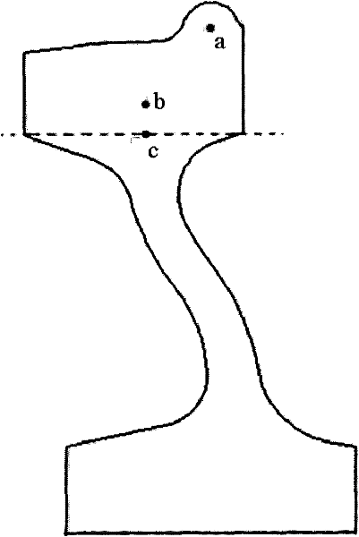
[0084] Take two railway wheels 1 with the same furnace number, the composition of which is shown in Table 1, and one of them has a pre-processed thermocouple temperature measuring hole, the position is as follows figure 2 Shown (a, b, c point among the figure); Another piece is the comparative example that adopts prior art. ( figure 2 It is a sectional view along the railway wheel 1 axis. )

[0085] The two railway wheels 1 are simultaneously subjected to normalizing at 820° C. for 1 hour, followed by annealing pretreatment at 710° C. to 740° C. for 1 hour.

[0086] Then using the above-mentioned device and the above-mentioned method of the present invention, the rim of a piece of railway wheel 1 processed with a temperature measuring hole is induction heated, and the temperature is set to 850 ° C, and the temperature measurement result inside the rim is as follows Figure 4 As shown, quenching and tempering are carried out after heating. ( Figure 4 The curves of a, b,...

Embodiment 2

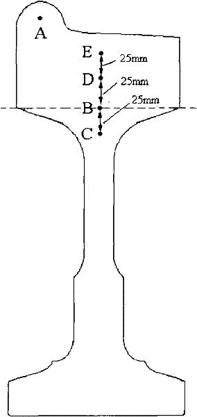
[0093] Take two railway wheels 1 with the same furnace number, the composition of which is shown in Table 1, and one of them has a pre-processed thermocouple temperature measuring hole, the position is as follows image 3 Show (A, B, C, D, E point among the figure); Another piece is the comparative example that adopts prior art. ( image 3 is a sectional view along the axis of the railway wheel 1. )

[0094] The two railway wheels 1 are simultaneously subjected to normalizing at 820° C. for 1 hour, followed by annealing pretreatment at 710° C. to 740° C. for 1 hour.

[0095] Then, using the above-mentioned device and the above-mentioned method of the present invention, the rim of a railway wheel 1 processed with a temperature measuring hole is induction heated, and the temperature is set to 860° C., and the temperature measurement result inside the rim is as follows Figure 5 As shown, quenching and tempering are carried out after heating. ( Figure 4 The A, B, C, D, E cu...


PUM


Abstract

The invention discloses a railway wheel heat treatment heating furnace. An induction heating device therein has the structure that the periphery of the tread of a railway wheel is provided with an induction heating coil, the corresponding positions of the inner side surface of the rim of the railway wheel and the inner side surface of the rim to a transition area are respectively provided with aninduction heating compensation coil. The invention also discloses a heat treatment process thereof of the heat treatment heating furnace. The above technical scheme realizes the technical target of high strength and high toughness of the rim as well as low strength and high toughness of a wheel disk. The two-phase region has high heating speed and short austenite temperature region, is favorable for evenly refining crystalline grains and improves rim toughness. The invention can realize quick heating of the wheel rim position, and the wheel disk position temperate is below Ac3 while the rim position is totally austenitized. The invention has the advantages of quick starting, high heating speed, easy control of temperature, high heating efficiency, favorable technical repeatability, favorable workpiece surface quality, environmental protection and the like.

Description

technical field [0001] The invention belongs to the technical field of metallurgical industry production, and relates to the manufacturing technology of railway wheels, more specifically, the invention relates to a heating furnace for heat treatment of railway wheels. In addition, the present invention also relates to the heat treatment process adopted by the heat treatment furnace. Background technique [0002] With the rapid development of my country's railway industry, the operating mileage and interval of high-speed EMUs are constantly expanding. At present, the key components of high-speed EMUs, including wheels, are all dependent on imports. Therefore, it is imperative to realize the localization of key components of high-speed EMUs. Masteel and the Ministry of Railways jointly undertook the research and development of high-speed EMU wheels. [0003] According to the preliminary trial production results, for CRH2 EMU wheels, there is a significant gap in the overall ...

Claims


Application Information

Patent Timeline
Patent Type & Authority Patents(China)
IPC IPC(8): C21D9/34C21D1/28C21D1/26C21D1/42C21D1/18
CPCY02P10/25
Inventor 钟斌江波王世付陈刚李翔赵海孙曼丽蒋培华
Owner MAANSHAN IRON & STEEL CO LTD
Why Eureka
Try Eureka