High-frequency gas-liquid switch valve

A valve, gas-liquid technology, applied in sliding valve, valve details, valve device and other directions, can solve the problems of polluted gas source, high air pressure requirements, high manufacturing cost, and achieve simple valve body structure, good sealing performance, and manufacturing cost. low effect

Active Publication Date: 2010-09-01
CHINA NAT HEAVY MACHINERY RES INSTCO
View PDF5 Cites 0 Cited by
  • Summary
  • Abstract
  • Description
  • Claims
  • Application Information

AI Technical Summary

Problems solved by technology

[0002] The single nozzle flow switch valves of the process lubrication system of cold rolling mills at home and abroad are roughly divided into three types: the first type is a cartridge valve that directly drives the valve core with an electromagnet. This type of valve has high manufacturing costs and requires on-site maintenance. The possibility is very low, if there is a failure, only the whole valve needs to be replaced; the second type is a cartridge valve that uses compressed air to drive the spool type. The cavity traps oil, and the liquid is easy to leak into the air cavity, polluting the air source, and the reliability of the valve core action is greatly reduced. At the same time, the plug-in form leads to high manufacturing costs of the installed valve plate; the third is to use compressed air to drive with an additional spring The spool-type plate-mounted valve has high requirements on air pressure in the air cavity. Because this type of valve has no valve sleeve, it is difficult to process the valve body, and the spool is easily stuck. There is only one seal for the spool, so it is difficult to ensure the air Real separation of liquid and liquid chambers

Method used


Image

  • High-frequency gas-liquid switch valve
  • High-frequency gas-liquid switch valve
  • High-frequency gas-liquid switch valve

Examples


Embodiment Construction

[0018] The present invention will be described in detail below in conjunction with the accompanying drawings.

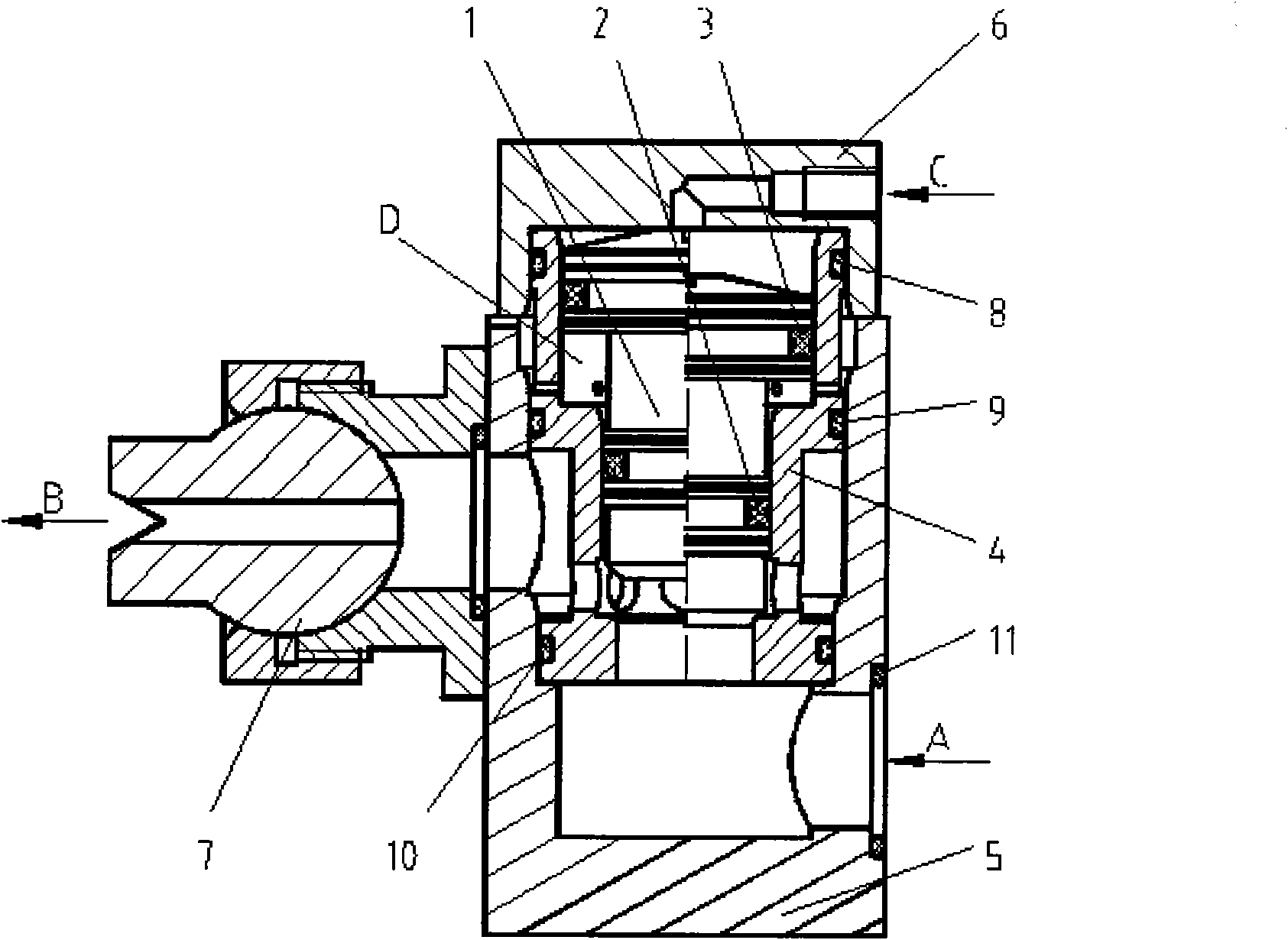
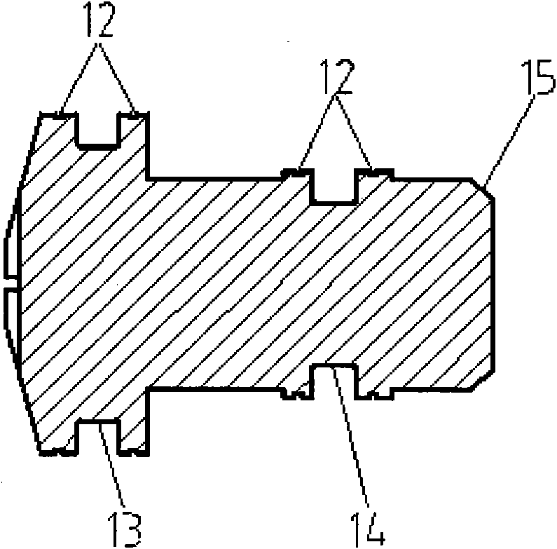
[0019] refer to figure 1 , a high-frequency gas-liquid switch valve, including a valve core 1, the valve core 1 is installed in the valve sleeve 4, the valve core 1 can slide in the valve sleeve 4, the valve sleeve 4 is installed in the inner cavity of the valve body 5, and the valve sleeve One end of 4 is installed in the end cover 6, the end cover 6 is fixed on the valve body 5, the nozzle 7 is fixed on the valve body 5 through the nozzle connection hole 25, and the fourth static seal 11 is installed in the static sealing groove of the valve body 5, The first dynamic seal groove 13 and the second dynamic seal groove 14 of the valve core 1 are respectively equipped with a first dynamic seal 2 and a second dynamic seal 3, and the first static seal groove 21 and the second static seal groove of the valve sleeve 4 The sealing groove 22 and the third static sealing gro...


PUM


Abstract

The invention discloses a high-frequency gas-liquid switch valve, which comprises a valve spool. The valve spool is arranged in a valve bush which is arranged in an inner cavity of a valve body; one end of the valve bush is arranged in an end cover which is fixed on the valve body; a nozzle is fixed on the valve body; a fourth static seal is arranged in a static seal groove of the valve body; first and second dynamic seals are arranged in a dynamic seal groove of the valve spool; first, second and third static seals are arranged in the static seal groove of the valve bush; when an air control port is communicated with the atmosphere, liquid with pressure enters the valve body through an inlet, passes through an inlet hole and a valve bush small hole and only acts on the minor-diameter end of the valve spool, the valve spool moves upwards, the air control port discharges air, and the liquid enters the nozzle through a connecting hole of the nozzle and is ejected through an outlet; and when the air control port is communicated with compressed air, the valve spool moves downwards until the lower-end conical surface of the valve spool is contacted with the conical surface of the valve bush so as to cut off the liquid flowing to the outlet. The high-frequency gas-liquid switch valve has the advantages of long service life, high reliability of actions of the valve spool, good sealing property, simple processing and low manufacturing cost.

Description

technical field [0001] The invention belongs to the technical field of switch valves for cold rolling mills, and in particular relates to a high-frequency gas-liquid switch valve. Background technique [0002] The single nozzle flow switch valves of the process lubrication system of cold rolling mills at home and abroad are roughly divided into three types: the first type is a cartridge valve that directly drives the valve core with an electromagnet. This type of valve has high manufacturing costs and requires on-site maintenance. The possibility is very low, if there is a failure, only the whole valve needs to be replaced; the second type is a cartridge valve that uses compressed air to drive the spool type. The cavity traps oil, and the liquid is easy to leak into the air cavity, polluting the air source, and the reliability of the valve core action is greatly reduced. At the same time, the plug-in form leads to high manufacturing costs of the installed valve plate; the th...

Claims


Application Information

Patent Timeline
Patent Type & Authority Applications(China)
IPC IPC(8): F16K3/16F16K31/12F16K3/30F16K27/04
Inventor 辛静泰甄永富
Owner CHINA NAT HEAVY MACHINERY RES INSTCO
Why Eureka
Try Eureka