Pulsating heat pipe heat-transfer device for low grade heat energy utilization

A pulsating heat pipe, low-grade technology, applied in tubular elements, heat exchange equipment, indirect heat exchangers, etc., can solve the problems of insufficient use of heat pipes, difficulty in adding fins, large heat transfer resistance, etc., and achieve compact structure , light weight, good heat transfer effect

Inactive Publication Date: 2010-09-01
CENT SOUTH UNIV
View PDF5 Cites 16 Cited by
  • Summary
  • Abstract
  • Description
  • Claims
  • Application Information

AI Technical Summary

Problems solved by technology

It is difficult to add fins to the pulsating heat pipe device bent by capillary tubes. The heat transfer resistance between the cold and hot fl...

Method used


Image

  • Pulsating heat pipe heat-transfer device for low grade heat energy utilization
  • Pulsating heat pipe heat-transfer device for low grade heat energy utilization
  • Pulsating heat pipe heat-transfer device for low grade heat energy utilization

Examples


Embodiment 1

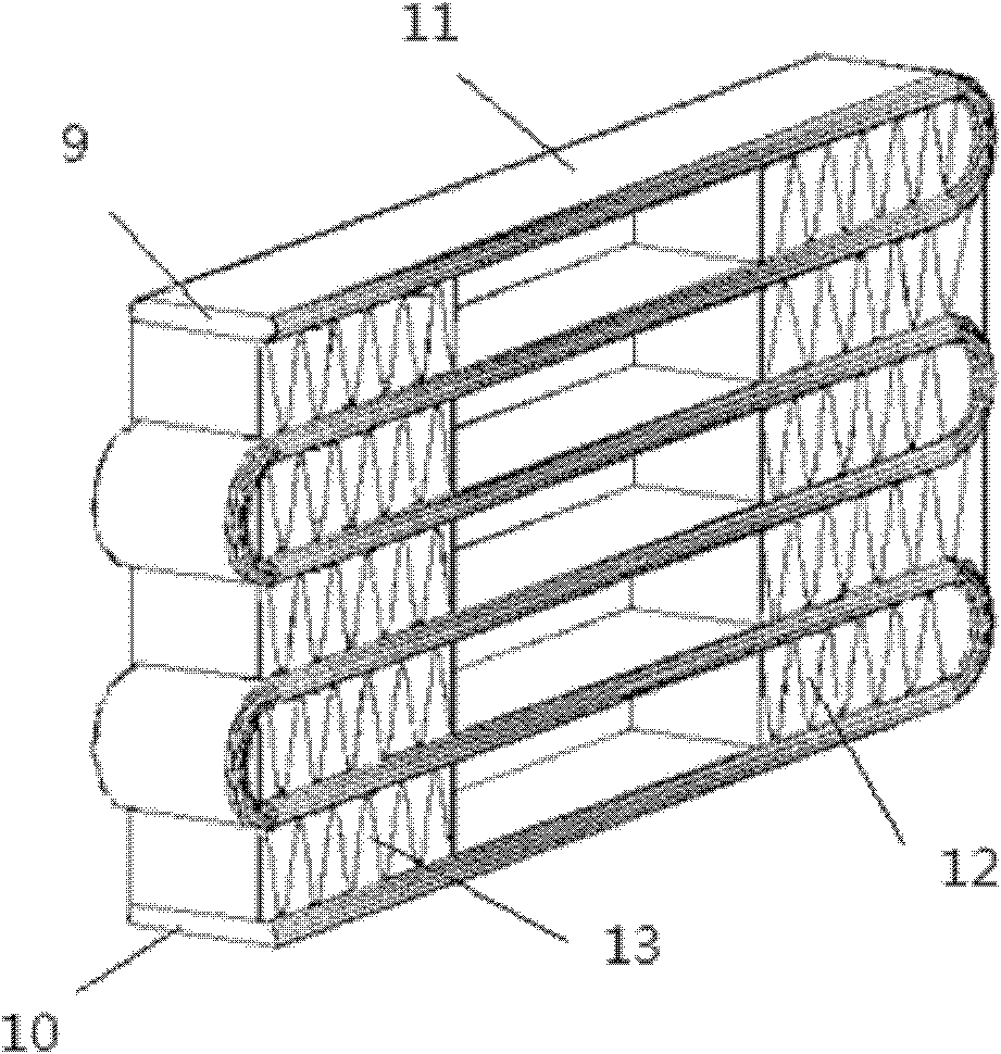
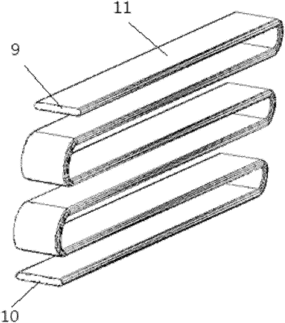
[0026] The single row of porous flat tubes 11, which are made of aluminum, are divided into many channels by a grille 14 in the middle and closed at both ends, and are bent into multiple layers, forming a heating section 17 and a cooling section 15, and the middle section is an adiabatic section 16. The channels are all square holes, which are more conducive to the heat transfer of the pulsating heat pipes. Each serpentine pipe in the single row of porous flat tubes 11 forms an open serpentine pipe respectively, thus forming several open-circuit pulsating heat pipes connected in parallel. The inside of the serpentine pipe is evacuated and filled with 30% ammonia by volume. Figure 8 It is a schematic diagram of the channel connection of this kind of pulsating heat pipe. Between the heating section 17 and the cooling section 15, two adjacent layers of single-row porous flat tubes 11 are brazed with corrugated fins 13 in the heating section and corrugated fins 12 in the cooling s...

Embodiment 2

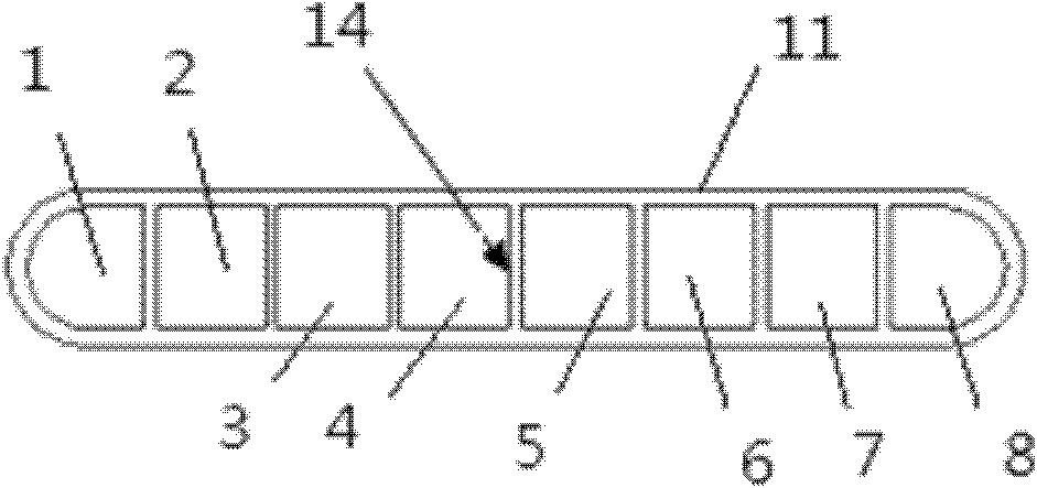
[0029] A single row of porous flat tubes made of copper is divided into many channels by a grid in the middle and closed at both ends, and is bent into multiple layers to form a heating section and a cooling section. The middle section is an adiabatic section 16, and all channels are square. holes, which are more conducive to the heat transfer of the pulsating heat pipe, and each passage in the single row of porous flat tubes 11 forms a serpentine pipe respectively, and then through further processing (taking 8 passages as an example, see figure 1 ): the first serpentine duct 1 and the second serpentine duct 2, the third serpentine duct 3 and the fourth serpentine duct 4, the fifth serpentine duct 5 and the sixth serpentine duct 6, the seventh serpentine duct 7 and the eighth serpentine duct 8 cut off a part of the grille 14 at the front end 9; at the same time, the second serpentine duct 2 and the third serpentine duct 3, the fourth serpentine duct 4 and the fifth serpentine d...

Embodiment 3

[0032] A single row of porous flat tubes 11 made of copper, divided into many channels by a grid 14 in the middle and closed at both ends, is bent into multiple layers, forming a heating section 17 and a cooling section 15, and the middle section is an adiabatic section 16. The passages are all square holes, which are more conducive to the heat transfer of the pulsating heat pipes. Each passage in the single row of porous flat tubes 11 forms a serpentine pipe respectively, and then through further processing (taking 8 passages as an example, see figure 1 ): between the first serpentine duct 1 and the second serpentine duct 2, the third serpentine duct 3 and the fourth serpentine duct 4, the fifth serpentine duct 5 and the sixth serpentine duct 6, the seventh serpentine duct A part of the grille 14 between the serpentine duct 7 and the eighth serpentine duct 8 is cut off at the front end 9 and the tail end 10 simultaneously, like this, the first serpentine duct 1 and the second ...


PUM


Abstract

The invention discloses a pulsating heat pipe heat-transfer device for low-grade heat energy utilization. A single-row multi-port flat tube with a plurality of channels is bent into a plurality of layers and after both ends of the flat tube are processed further, different connecting modes can be formed, so that the device works according to the mechanism of an open ended or loop pulsating heat pipe. Moreover, wavy fins can be additionally arranged between two adjacent layers of flat tubes of a cooling section and a heating section of the heat-transfer device as required to reduce the heat transfer resistances of the cooling section and the heating section. When the pulsating heat pipe heat-transfer device is used, heating fluid passes through one end of the device, and cooling fluid passes through the other end of the device, so that utilization of low-grade heat or cooling and heat dissipation is realized. The pulsating heat pipe heat-transfer device provided by the invention has the advantages of compact structure, light weight, low cost, simple manufacturing, good heat-transfer effect and the like.

Description

technical field [0001] The invention relates to a pulsating heat pipe heat transfer device, which is suitable for the utilization of low-grade heat and the heat dissipation of heat-generating components. Background technique [0002] With the development of the economy, the shortage of energy is becoming more and more serious. The rational use of energy, especially the rational use of low-grade heat (such as solar energy, industrial waste heat, etc.) has attracted much attention. The equivalent heat transfer of the heat pipe is hundreds or even thousands of times that of the best metals such as silver, copper, aluminum, etc., so it is called "near superconductor". The application of heat pipes in some low-grade heat utilization devices (such as flue gas waste heat recovery, etc.) has achieved certain results. However, the inner wall of the traditional heat pipe must have a liquid-absorbing core material, so the size of the heat pipe is large and the weight is increased, wh...

Claims


Application Information

Patent Timeline
IPC IPC(8): F28D15/02F28F1/12
CPCF28D15/0266F28D15/0233
Inventor 曹小林曹双俊张建华段飞孙俊杰赵珫李政张高鹏
Owner CENT SOUTH UNIV
Why Eureka
Try Eureka