Coupling type intelligent bearing monitoring device arranged on bearing

A monitoring device and a coupled technology, applied in the field of coupled intelligent bearing monitors, can solve the problems of reduced signal transmission intermediate interface, bearing stress concentration, submerged fault information, etc., so as to improve reliability and effectiveness, and reduce bearing stress. Concentrated, easy to install and remove effects

Active Publication Date: 2010-09-01
CHONGQING UNIV
View PDF4 Cites 19 Cited by
  • Summary
  • Abstract
  • Description
  • Claims
  • Application Information

AI Technical Summary

Problems solved by technology

The external combination method does not destroy the structure of the bearing but changes the overall size of the traditional bearing. At the same time, the characteristics of this type of combination determine that there is a certain distance between the sensing component and the source of the fault, so that the acquired signal cannot truly reflect the bearing. This method cannot be used for early detection of bearing fault characteristics, because the bearing fault detection with this structure cannot guarantee the reliability of the signal; the embedded combination method is very close to the source of the measured signal, and the signal The intermediate interface of transmission is reduced, the collected signal can truly reflect the actual working condition of the bearing, and the signal-to-noise ratio is high, but this structure destroys the integrity of the bearing, and it is easy to cause problems such as stress concentration, so this structure is also important for bearing state detection. there are certain problems
[0003] At present, most of the methods for testing the working performance of bearings using the combination of plug-in and embedded structures are mostly to obtain the vibration signal of the bearing through the piezoelectric strain gauge acceleration sensor device, and the piezoelectric strain gauge The chip acceleration sensor device mainly obtains the high-frequency information of the bearing, and the frequency range of the obtained signal is very wide, and it contains background noise and various interference signals, so that the fault information of the bearing is submerged in the broadband signal
Vibration signals acquired by piezoelectric strain gauge acceleration and speed sensing devices generally rely on techniques such as shock pulse method and resonance demodulation to extract the required fault characteristics, but such methods cannot effectively select the range of resonance frequency bands , which brings difficulties to the subsequent fault feature extraction, so it is difficult to really get a satisfactory fault recognition effect
There are two existing combination methods. The sensing unit with the speed device cannot realize multi-parameter synchronous trigger acquisition, and this synchronous trigger acquisition plays a vital role in the subsequent bearing fault diagnosis. Periodic sampling can extract fault information more efficiently
[0004] The disadvantages of the existing technology are: the signal obtained by the external structure cannot truly reflect the fault information of the bearing, and the embedded structure destroys the internal structure of the bearing, causing the stress concentration problem of the bearing, and the fault information of the bearing is submerged in this In the broadband signal, the low-frequency features of the bearing cannot be effectively extracted, let alone the synchronous trigger acquisition of multi-parameter bearings

Method used


Image

  • Coupling type intelligent bearing monitoring device arranged on bearing
  • Coupling type intelligent bearing monitoring device arranged on bearing
  • Coupling type intelligent bearing monitoring device arranged on bearing

Examples


Embodiment 1

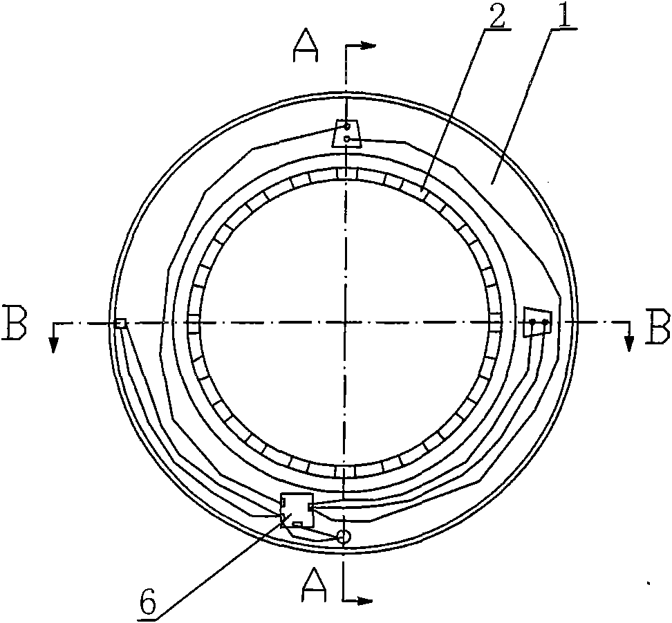
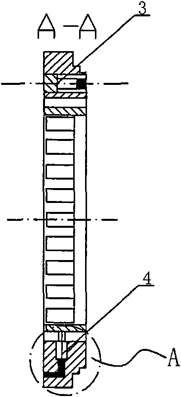
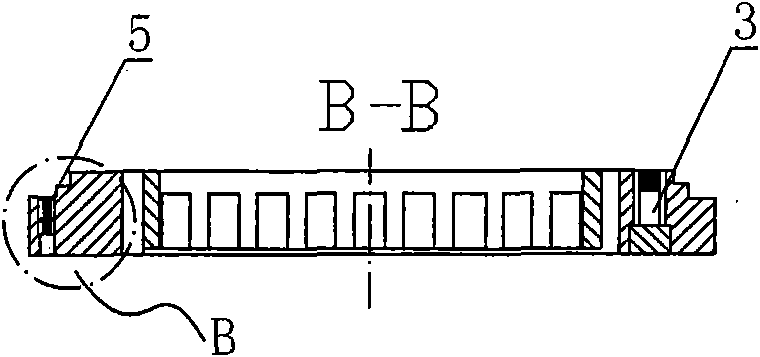
[0059] Such as Figures 1 to 4 As shown, a coupled intelligent bearing monitoring device installed on a bearing includes a housing 1 and a rotational speed code disc 2. The rotational speed code disc 2 is a circular code disc coaxial with the housing 1. The intelligent monitor Axially inserted into the gap between the rotating ring and the fixed ring of the bearing and interference fit with the bearing;

[0060] Two strain gauge type acceleration sensing devices 3, a rotational speed sensing device 4 and a temperature sensing device 5 are embedded in the housing 1, and the centerlines of the two strain gauge type acceleration sensing devices 3 are both Parallel to the centerline of the housing 1, the angle between the two is 90°, the rotational speed sensing device 4 is embedded radially on the housing 1, and the centerline of the temperature sensing device 5 Parallel to the center line of the housing 1, a circuit board 6 is installed on the end face of the housing 1, the two...

Embodiment 2

[0083] Such as Figures 13 to 15 As shown, the rotational speed code disc 2 is set outside the housing 1 .

[0084] In this implementation, the smart bearing monitor is installed on a bearing whose outer ring rotates and the inner ring does not move. The housing 1 of the smart bearing monitor is set in the speed code disc 2. Other structures and working principles are the same as those of the above-mentioned embodiment. same.


PUM


Abstract

The invention discloses a coupling type intelligent bearing monitoring device arranged on a bearing. The coupling type intelligent bearing monitoring device is characterized by comprising a shell and a rotating speed coded disk, wherein the rotating speed coded disk is a round coded disk coaxial with the shell; an intelligent monitor is axially inserted into a gap between a rotating ring and a fixed ring of the bearing and forms an interference fit with the bearing; and two strain gage type acceleration sensing devices, a rotating speed sensing device and a temperature sensing device are embedded in the shell and all connected with a circuit board on the end face of the shell through a signal output line. The invention has the obvious advantages that the low-frequency-band characteristics of the bearing can be effectively extracted; the reliability and the effectiveness of signals are improved; all the sensing devices are used as a part of the intelligent bearing and easy to mount and demount, and the damage to the bearing structure and the bearing stress are reduced; and sampling is triggered by the rotating speed, thereby realizing the synchronous trigger acquisition of multiple parameters of the bearing.

Description

technical field [0001] The invention belongs to monitoring equipment, in particular to a coupled intelligent bearing monitor applied to bearing state detection. Background technique [0002] The current integrated smart bearings have two structural forms: external and embedded. The external combination method does not destroy the structure of the bearing but changes the overall size of the traditional bearing. At the same time, the characteristics of this type of combination determine that there is a certain distance between the sensing component and the source of the fault, so that the acquired signal cannot truly reflect the bearing. This method cannot be used for early detection of bearing fault characteristics, because the bearing fault detection with this structure cannot guarantee the reliability of the signal; the embedded combination method is very close to the source of the measured signal, and the signal The intermediate interface of transmission is reduced, the c...

Claims


Application Information

Patent Timeline
Patent Type & Authority Applications(China)
IPC IPC(8): G01M13/04G01P15/00G01P3/42G01K7/22
Inventor 邵毅敏李小侠周平周晓君陈再刚王辉孙婷婷李杰
Owner CHONGQING UNIV
Why Eureka
Try Eureka