Construction process for reclamation by hydraulic filling of silt and device thereof

A technology of filling and filling silt and construction device, which is applied in soil protection, infrastructure engineering, construction, etc., can solve the problems of slow silt deposition and inability to follow-up construction.

Inactive Publication Date: 2011-12-21
武汉华荣科技发展有限责任公司
View PDF0 Cites 2 Cited by
  • Summary
  • Abstract
  • Description
  • Claims
  • Application Information

AI Technical Summary

Problems solved by technology

Therefore, it can solve the problem that the silt deposition is slow and the follow-up construction cannot be carried out quickly in the land reclamation

Method used


Image

  • Construction process for reclamation by hydraulic filling of silt and device thereof
  • Construction process for reclamation by hydraulic filling of silt and device thereof
  • Construction process for reclamation by hydraulic filling of silt and device thereof

Examples


Embodiment 2

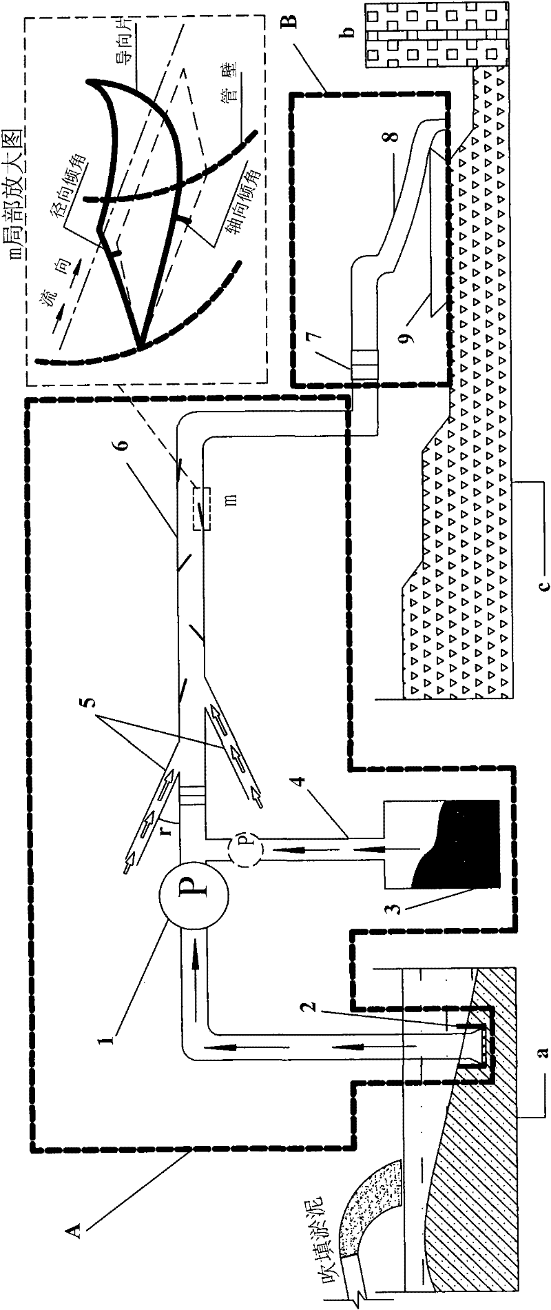
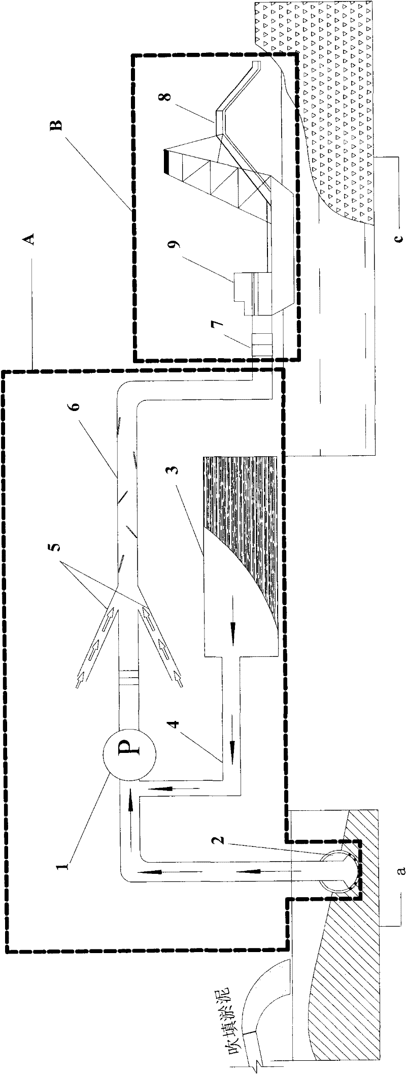
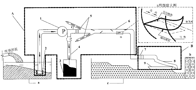
[0034] A seashore reclamation site uses the construction device for dredging silt reclaiming of the present invention. The specific devices and specifications of each device are as follows: Solidification treatment system A: Pumping device 1 includes mud pumps and inner diameters selected according to actual needs 80mm front and rear piping of the pump. The debris screening device 2 is a porous cuboid structure with a certain sieve aperture. The curing agent storage device 3 is 8m 3 The cylinder is used to store the slag cement. The curing agent delivery device 4 is a pipe with an inner diameter of 20 mm with a screw propeller on the inner wall, and the pipe is connected to the front pipe of the pump. The compressed air conveying device 5 includes an air compressor with a power of 2.5 kW and a compressed air conveying pipe with an inner diameter of 15 mm, which is located at the beginning of the mixed mud mixing conveying device 6. The mixed mud mixing and conveying device 6 ...

Embodiment 3

[0038] A coastal roadbed project uses the construction device for dredging and filling silt to make land of the present invention. The specific devices and specifications of each device are as follows: Solidification treatment system A: Pumping device 1 includes a slurry pump selected according to actual needs and an inner diameter of 150mm The pipeline before the pump and the pipeline after the pump. The debris screening device 2 is a porous spherical structure with a certain sieve aperture. The curing agent storage device 3 is 3×3×3m 3 The square tube is used to store ordinary silica cement and lime mixture. The curing agent delivery device 4 is a pipe with an inner diameter of 40 mm connected to the pipe before the pump, and a pump with a power of 3 kW is connected in the middle of the pipe. The compressed air delivery device 5 includes an air compressor with a power of 5 kW and three compressed air delivery pipes with an inner diameter of 10 mm. The mixed mud mixing and c...


PUM


Abstract

The invention discloses a construction process for the reclamation by the hydraulic filling of silt and a device thereof. The device comprises a solidification treatment system A and a paving system B for improved slurry, wherein the A comprises a pumping device, an impurity screening device, a solidification agent storage device, a solidification agent conveying device, a compressed air conveying device and a mixed slurry stirring and conveying device; the B comprises a connecting pipe section, a hose or belt conveyer and a bearing and moving device. The construction flow comprises the following steps of: (1) filling the silt slurry into a filling region or sedimentation tank so as to form a stacked layer of thick silt slurry; (2) pumping the thick silt slurry with the pumping device, conveying the solidification agent into the thick silt slurry at the same time, and mixing the thick silt slurry and the solidification agent in a pipe in front of or behind a pump so as to form the mixed slurry; (3) conveying the mixed slurry to the stirring and conveying device to form the improved slurry; (4) conveying the improved slurry out to the paving system B through the connecting pipe section; and (5) laying the improved slurry to specified thickness by the paving system B. The device is characterized by fast, high-efficiency, simple and convenient operation.

Description

Technical field [0001] The invention relates to a construction technology and a device for creating land by dredging silt, and belongs to the technical field of civil engineering foundation treatment. Background technique [0002] In recent years, my country’s coastal areas, such as the Bohai Bay area, the Yangtze River Delta, the Pearl River Delta, and the Beibu Gulf, are rapidly advancing the reclamation project from the sea. Since 2005, the coastal area of ​​China has been reclaiming land from the sea every year over 100 square kilometers. The area of ​​reclaimed land in 2009 has reached 150 square kilometers. At present, most of my country's land reclamation projects use the dredging silt land reclamation method, that is, the submarine silt is blown into the enclosure, and the silt is transformed into a foundation with a certain bearing capacity after a certain treatment. [0003] At present, the main method for treating these dredging silt is to use the drainage consolidation ...

Claims


Application Information

Patent Timeline
Patent Type & Authority Patents(China)
IPC IPC(8): E02D3/12
Inventor 程寅黄新
Owner 武汉华荣科技发展有限责任公司
Why Eureka
Try Eureka