Self energy supply lightning current detection system

A detection system and lightning current technology, applied in the direction of current indication, measurement of current/voltage, measurement devices, etc., can solve the problems of method limitation, heavy workload, and only one-time recording, etc., to achieve good safety features and energy harvesting Convenience and ease of installation

Inactive Publication Date: 2010-09-08
CHONGQING UNIV
View PDF5 Cites 25 Cited by
  • Summary
  • Abstract
  • Description
  • Claims
  • Application Information

AI Technical Summary

Problems solved by technology

The advantage of this method is that the cost is low and it is easy to install in large quantities, but the disadvantage is that the formula of the magnetic steel rod and the production process are scattered, and the measurement results themselves have large errors, and the time of lightning occurrence cannot be recorded, and only a single record can be obtained to obtain data inconvenient, heavy workload
[0004] Utility model 200720173616.4 "a lightning current detection device" solves the problem of detecting whether the arrester is struck by lightning. Although the device has a simple structure and low cost, it can only indicate whether the arrester has been struck by lightning, and cannot accurately locate the time, polarity and The magnitude of the amplitude, and the placement position will interfere with the magnetic field of the device itself, affecting the measurement accurac

Method used


Image

  • Self energy supply lightning current detection system
  • Self energy supply lightning current detection system
  • Self energy supply lightning current detection system

Examples


Embodiment Construction

[0048] Hereinafter, preferred embodiments of the present invention will be described in detail with reference to the accompanying drawings. It should be understood that the preferred embodiments are only for illustrating the present invention, but not for limiting the protection scope of the present invention.

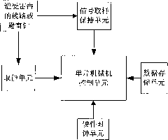
[0049] like figure 1 and figure 2 As shown, the self-powered lightning current detection system of the present invention is used in conjunction with the lightning protection device to realize the detection of lightning current related parameters, including a signal sampling and holding unit, an energy harvesting device, a single-chip microcomputer control unit 1, a hardware clock unit 2 and data storage unit 3;

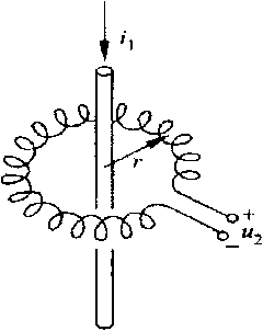
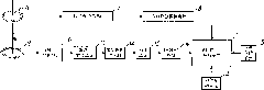
[0050] like image 3 As shown, the signal sampling and holding unit includes a current sensing unit 4, a voltage limiting protection unit 17 and a positive / negative peak holding unit 8 connected in sequence, the current sensing unit 4 adopts a Rogowski coi...


PUM


Abstract

The invention discloses a self energy supply lightning current detection system, which is used for being matched with a lightning rod device for use to realize the defection on relevant parameters of lightning current. The self energy supply lightning current detection system comprises a signal sampling maintaining device, an energy taking device, a single chip control unit, a hardware clock unit and a data storage unit, wherein the signal sampling maintaining device comprises a current sensing unit, a first voltage limiting protection unit and a positive/negative peak value maintaining unit which are connected in sequence, and the energy taking device comprises an energy taking coil, a front end protector, a rectifying and wave-filtering unit, a second voltage limiting protection unit, a voltage stabilizing unit and a DC/DC unit which are connected in sequence. The self energy supply lightning current detection system of the invention can continuously realize the monitoring on whether a transmission line or a building lightning rod suffers with the lightning strike or not, and can accurately record the time, the amplitude value in the occurrence of the lightning strike and the polarity, a special triggering circuit is not needed, and the invention has the characteristics of high precision, simple structure, small size, low cost, high safety and the like.

Description

technical field [0001] The invention belongs to the technical field of lightning current monitoring, and particularly relates to a self-powered lightning current detection system, which is specifically applicable to lightning current amplitude, polarity, and occurrence time of lightning rods and lightning arresters of overhead transmission lines in electric power systems, substations, and buildings. real-time monitoring. Background technique [0002] With the development of the national economy, the voltage level and scale of the power system develop and expand rapidly. The overhead transmission lines of the power system are widely distributed and are easily attacked by lightning. Substations and buildings are often attacked by lightning. Due to the randomness and shortness of occurrence, it is particularly important to accurately locate the time and characteristics of lightning current occurrence. The parameter characteristics of lightning current are of great significance...

Claims


Application Information

Patent Timeline
IPC IPC(8): G01R19/00G01R19/175G01R19/14G01R31/08
Inventor 杜林杨庆司马文霞袁涛陈伟根王有元李成祥李欣
Owner CHONGQING UNIV
Why Eureka
Try Eureka