
High-power LED phase-change cooling device

A phase-change cooling, high-power technology, applied in electrical components, circuits, semiconductor devices, etc., can solve the problem of difficult and reliable cooling of high-power LEDs, unfavorable marketization of high-power LEDs, and complex capillary structures. Low cost, strong practicability, good heat dissipation reliability

Inactive Publication Date: 2012-01-11
赵继永
View PDF0 Cites 0 Cited by
  • Summary
  • Abstract
  • Description
  • Claims
  • Application Information

AI Technical Summary

Problems solved by technology

When using heat pipes for lighting, if the heat pipes are bent, the cooling efficiency will drop sharply due to the fact that the gas and liquid in the traditional heat pipes are in the same pipe
However, in order to meet the needs of styling, the heat pipe of high-power LED must be bent, so the traditional heat pipe is difficult to reliably solve the cooling problem of high-power LED
In addition, the existing loop heat pipe technology is directly used in the heat dissipation of high-power LEDs, such as high manufacturing cost, inconvenient processing, and too complicated capillary structure, etc., cooling with traditional heat pipes is not conducive to the marketization of high-power LEDs

Method used


Image

  • High-power LED phase-change cooling device
  • High-power LED phase-change cooling device

Examples


Embodiment Construction

[0014] When the phase change material changes from one state to another, it needs to absorb or release heat from the environment, so that heat storage and release can be achieved, and the purpose of temperature control can be achieved. When the liquid state changes to a gas state, a large amount of heat is absorbed, and when the gas state is condensed into a liquid state, it releases heat. At the same time, the phase change process is generally isothermal or nearly isothermal. The use of phase change materials can achieve small The temperature of the environment is controlled, and it can be reused many times.

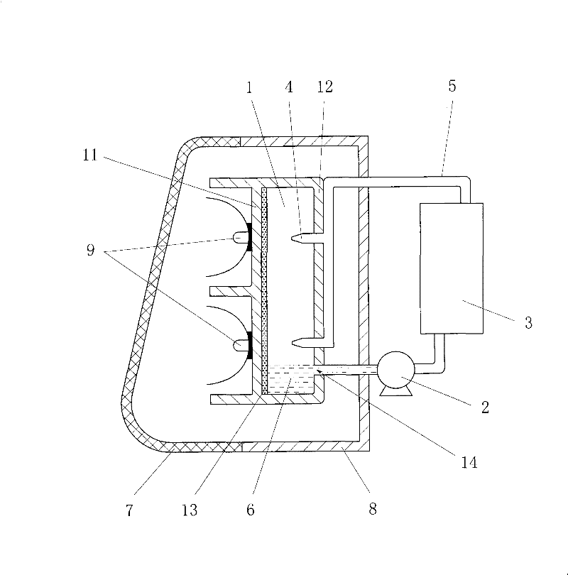
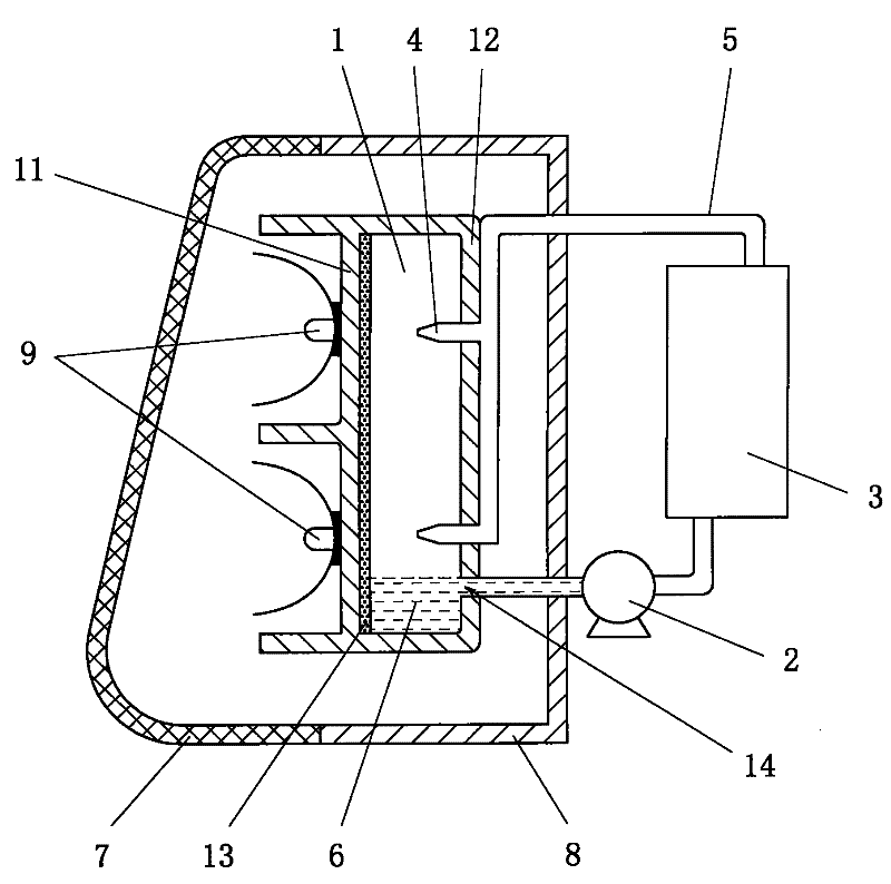
[0015] see figure 1 The high-power LED has a transparent lampshade 7 arranged in the front of the LED lamp 9 and a rear cover 8 connected to the transparent lampshade 7 at the rear of the LED lamp 9. The phase change cooling device of the high-power LED has a transparent lampshade 7 and The evaporation chamber 1 in the back cover 8, the nozzle 4 arranged in the evaporatio...


PUM


Abstract

The invention relates to a high-power LED phase-change cooling device comprising an evaporating chamber, a circulating pump, a condensing heat radiator and a nozzle, wherein the evaporating chamber is a closed shell and is provided with an evaporating plate and a back plate which are oppositely arranged; the evaporating plate is a metal plate; the outer side of the evaporating plate is welded with an LED lamp, and the inner side of the same is connected with a porous metal plate or a screen mesh; the nozzle is arranged at the inner side of the back plate and points to the evaporating plate; the circulating pump and the condensing heat radiator are arranged outside the evaporating chamber; the shell of the evaporating chamber is provided with an outlet positioned below the nozzle; a pipeline is sequentially connected with the outlet of the evaporating chamber, the circulating pump and the condensing heat radiator and then communicated with the nozzle by penetrating through the back plate of the evaporating chamber so that a closed loop is formed by the evaporating chamber, a micropump and the condensing heat radiator; and the evaporating chamber is internally provided with a cooling working medium. The invention has the advantages of good radiating reliability, high radiating efficiency, compact structure, convenient processing, low manufacturing cost and higher practicality, and is suitable for industrialized batch production.

Description

Technical field [0001] The present invention relates to a cooling device for high-power electronic or optical devices, in particular to a cooling device for a high-power LED (light emitting diode). Background technique [0002] The traditional cooling method of high-power devices usually transfers the heat generated by the heating device to the atmosphere outside the device by means of conduction and convection, etc., to achieve temperature control inside the device. For the harsh working environment, the heat flux density exceeds 100W / CM 2 For high-power LEDs, the internal heat is difficult to cool the high-power LEDs through the above-mentioned traditional methods. Preventing the LED temperature from rising too high is the core problem that must be solved in the application of high-power LED devices. At present, methods of improving LED substrate materials and packaging structures are widely used at home and abroad to improve the heat dissipation of high-power LEDs. But for hi...

Claims


Application Information

Patent Timeline
Patent Type & Authority Patents(China)
IPC IPC(8): H01L33/00
Inventor 赵继永
Owner 赵继永
Learn More