Optical fiber barrier finder

A technology of obstacle finder and optical fiber, which is applied in the direction of transmission monitoring/testing/fault measurement system, electromagnetic wave transmission system, electrical components, etc. It can solve the problems of inaccurate measurement results, affecting measurement results, and different sensitivities. The effect of simplicity, long test distance and small test result error

Inactive Publication Date: 2010-09-08
上海光家仪器设备有限公司
View PDF0 Cites 1 Cited by
  • Summary
  • Abstract
  • Description
  • Claims
  • Application Information

AI Technical Summary

Problems solved by technology

[0006] Obstacle finders currently on the market can measure reflection events and calculate the location of the fault point, but due to its internal structure, some settings are required, otherwise the measurement results will be inaccurate, such as: setting the optical pulse width, different pulse widths Measure different distance segments; Threshold value setting, the set threshold value is not the same, the measured sensitivity is also different
These settings directly affect the measurement results, and it is not suitable for inexperienced people to use this instrument
[0007] In addition, the measurement range of the obstacle finder currently on the market is relatively small. Due to its internal structure, the measurement range is 50m.

Method used


Image

  • Optical fiber barrier finder
  • Optical fiber barrier finder
  • Optical fiber barrier finder

Examples


Embodiment Construction

[0014] Below in conjunction with accompanying drawing and specific embodiment the present invention is described in further detail:

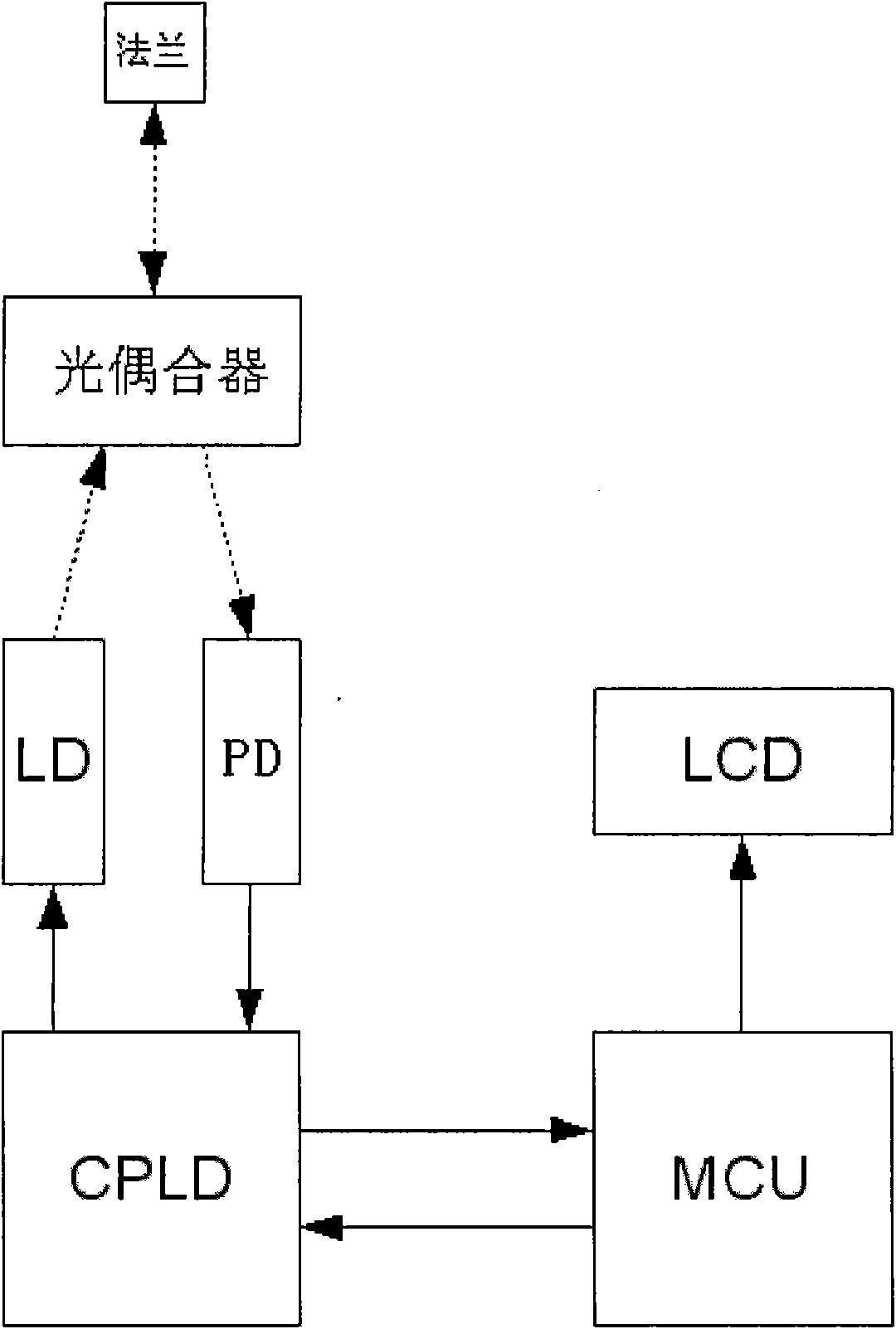
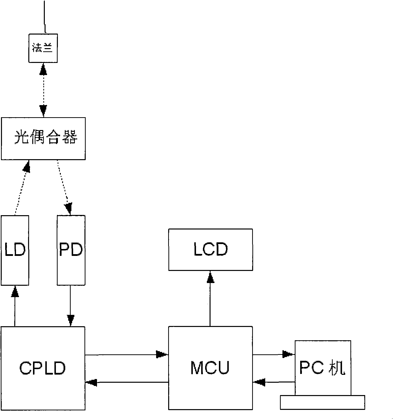
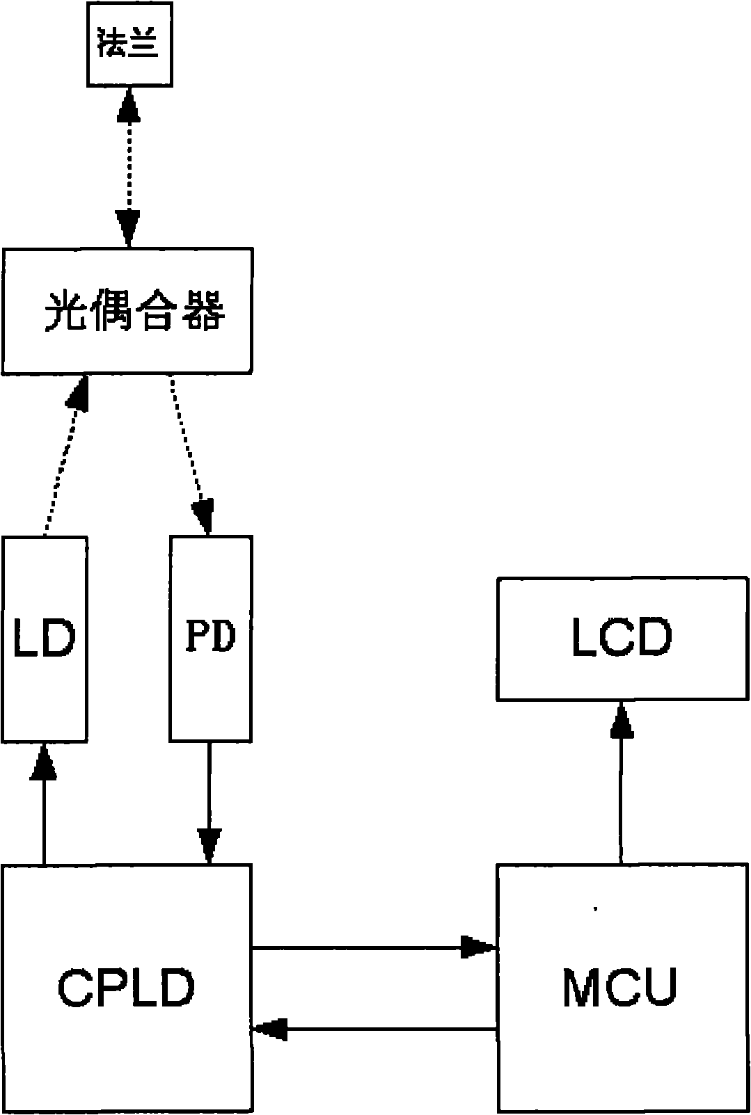
[0015] Depend on figure 1 Visible: the present invention comprises: flange, optical coupler; Also comprise: CPLD; CPLD controls LD laser to send the optical pulse of different pulse width, and receives PD detector signal; CPLD is also connected with MCU; Described optical coupler is The light emitted by the LD laser is coupled with the light entering the flange, the light emitted by the LD laser is emitted to the flange through the coupler, and the light entering the flange enters the PD detector through the coupler.

[0016] Described MCU is also connected with LCD;

[0017] The CPLD is also externally connected with a high-speed clock circuit.

[0018] The present invention aims at the deficiency of the existing OTDR and the problems existing in the optical fiber fault finder, and provides a digital optical fiber fault finder with convenient...


PUM


Abstract

The invention relates to an optical fiber barrier finder which comprises a flange and an optical coupler, and also comprises a CPLD (Complex Programmable Logic Device), wherein the CPLD controls an LD (Laser Device) to transmit optical pulses with different pulse widths and receives a PD (Photoelectric Diode) detector signal; the CPLD is also connected with an MCU (Microprogram Control Unit); the optical coupler is used for coupling light emitted by the LD and light emitted by the flange; and the light emitted by the LD is transmitted out from the flange through the coupler, and the light entering from the flange enters a PD detector through the coupler. The invention has the advantages of high operation speed, strong working property, long test distance, little test result error, simple structure, low cost, small volume, portability and audio-visual display.

Description

technical field [0001] The invention relates to an optical measuring instrument, in particular to a circuit module of an optical fiber obstacle finding instrument. Background technique [0002] Standing out from optical communication, optical fiber communication technology has become one of the main pillars of modern communication and plays a pivotal role in modern telecommunication networks. As an emerging technology, optical fiber communication has been developing rapidly and widely used in recent years, which is rare in the history of communication. It is also an important symbol of the world's new technology revolution and the main transmission tool for various information in the future information society. [0003] Optical fiber is currently the transmission medium of light in optical communication, and the physical characteristics of optical fiber are fragile, fragile, and easy to break, so the installation and maintenance of optical fiber is very important. The trans...

Claims


Application Information

Patent Timeline
Patent Type & Authority Applications(China)
IPC IPC(8): H04B10/08H04B10/07
Inventor 阮志光施钟民
Owner 上海光家仪器设备有限公司
Why Eureka
Try Eureka