Bearing device for wheel

A bearing device and wheel technology, applied to bearings, axles, wheels, etc., can solve the problems of poor component management, poor workability, and large number of components, and achieve the effects of excellent productivity and improved strength

Active Publication Date: 2010-09-08
NTN CORP
View PDF4 Cites 9 Cited by
  • Summary
  • Abstract
  • Description
  • Claims
  • Application Information

AI Technical Summary

Problems solved by technology

Therefore, screw tightening work is required at the time of assembly, and workability is poor, and the number of parts is large, and parts management is also poor.

Method used


Image

  • Bearing device for wheel
  • Bearing device for wheel
  • Bearing device for wheel

Examples


Embodiment Construction

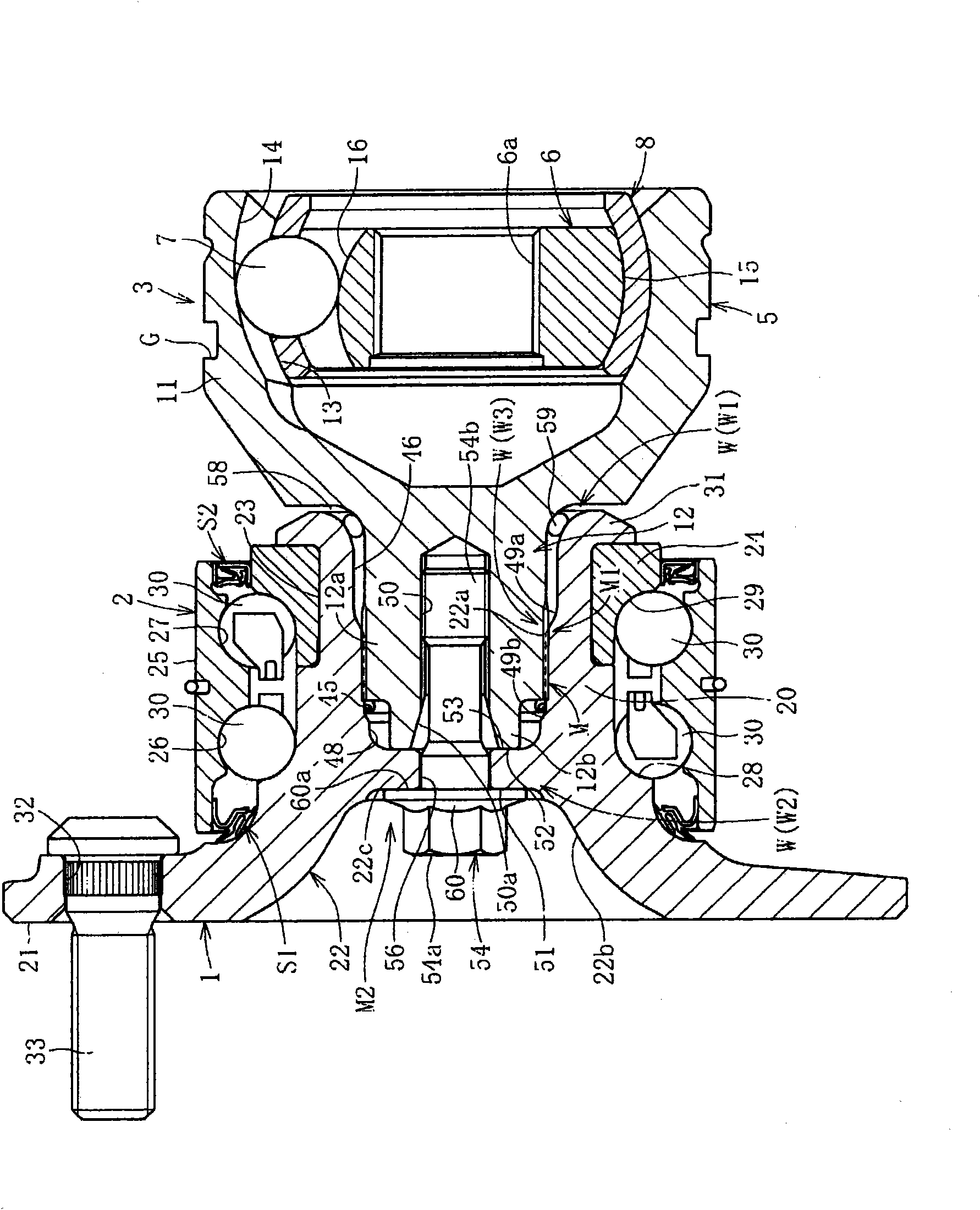
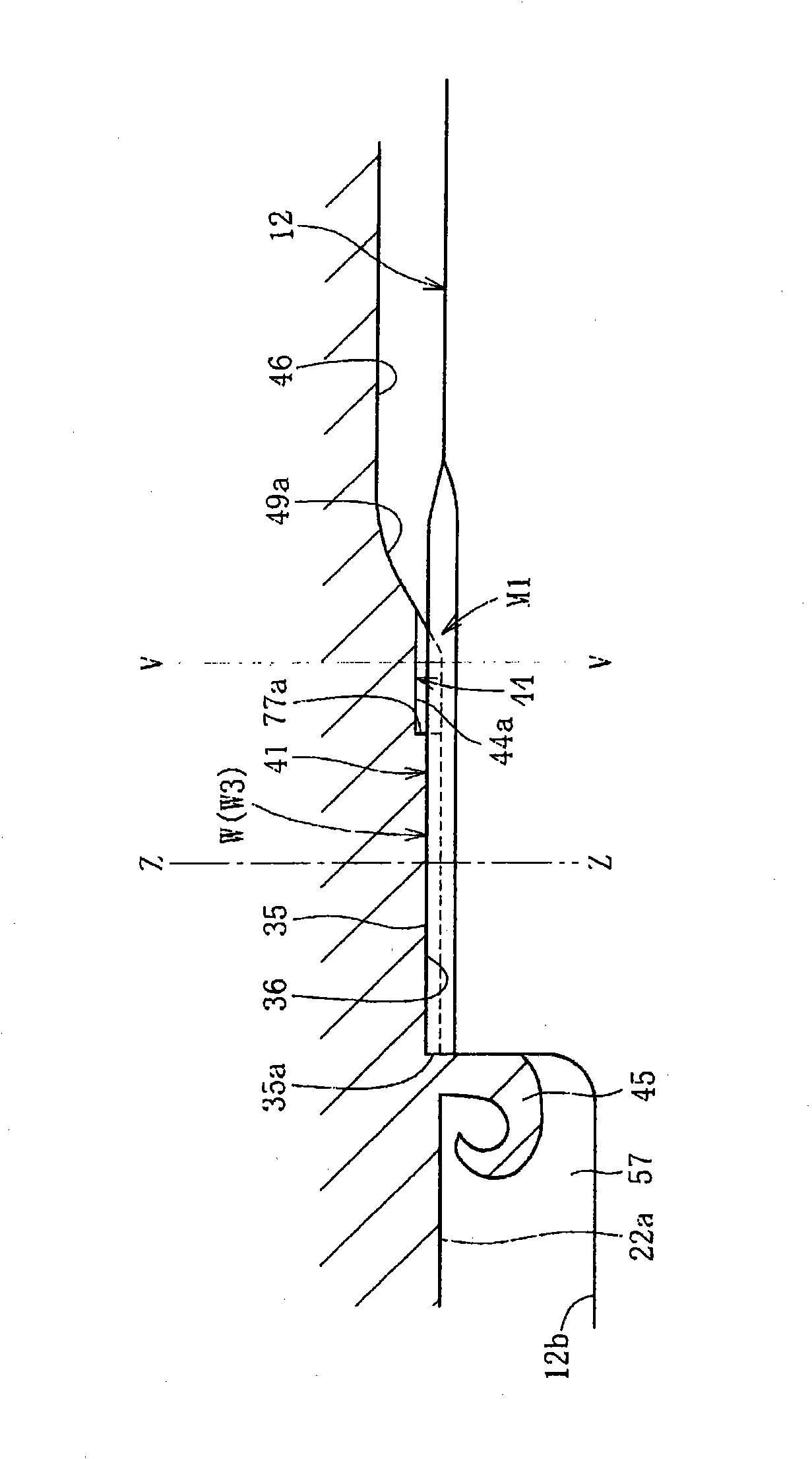
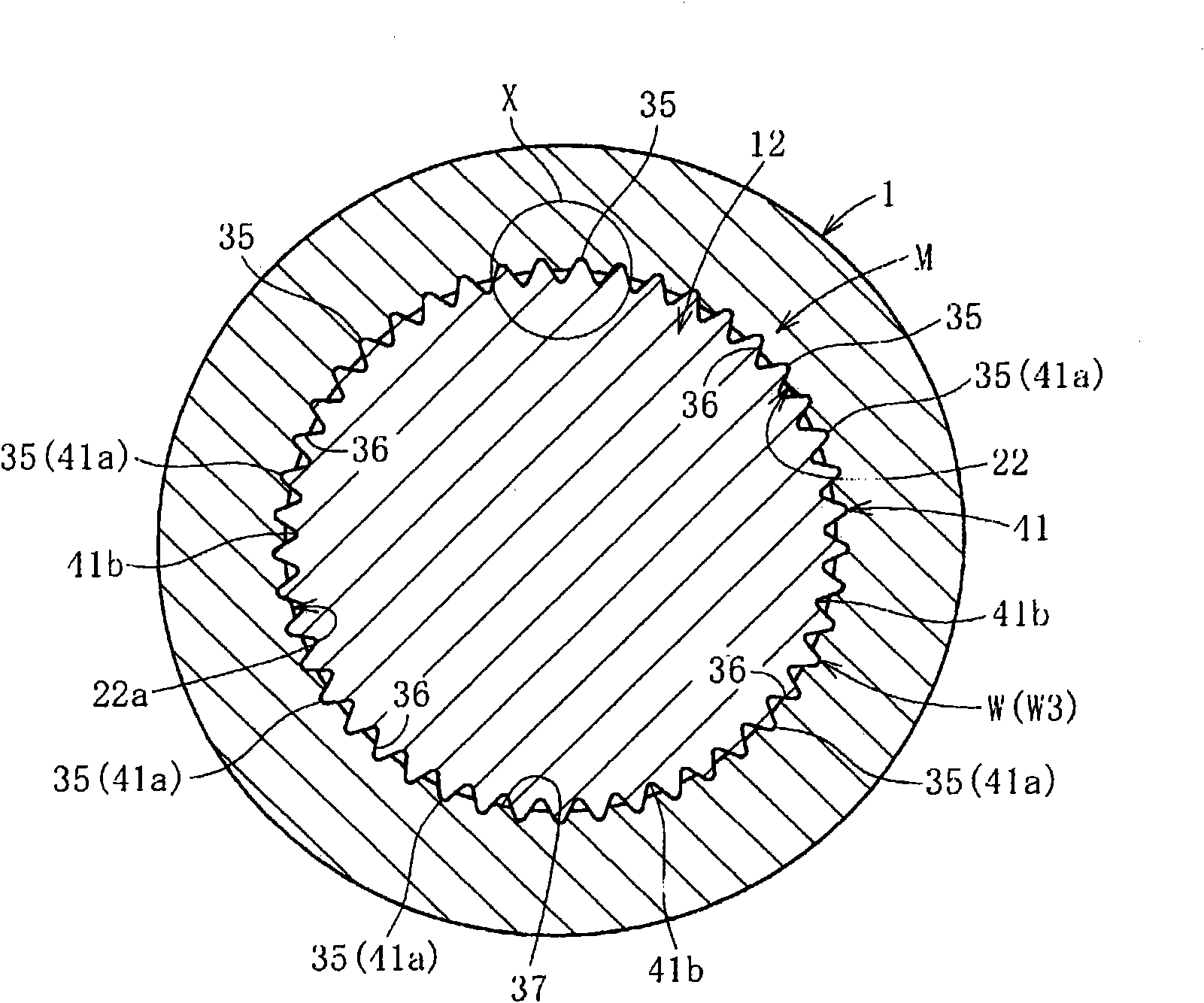
[0105] Below, based on Figure 1 ~ Figure 1 4. Embodiments of the present invention will be described. figure 1 shows a bearing device for a wheel according to the first embodiment. This bearing device for a wheel integrates a hub ring 1, a multi-row rolling bearing 2, and a constant velocity universal joint 3, and integrates the hub ring 1 and the The shaft portion 12 of the outer joint member of the constant velocity universal joint 3 in the hole portion 22 is detachably coupled via the concave-convex fitting structure M. As shown in FIG.

[0106] The constant velocity universal joint 3 is composed of the following main components: an outer ring 5 as an outer joint member; an inner ring 6 as an inner joint member arranged inside the outer ring 5; A plurality of balls 7 for transmitting torque; a cage 8 interposed between the outer ring 5 and the inner ring 6 and holding the balls 7 . Such as Figure 8 , etc., the inner ring 6 is coupled to the shaft 10 in a torque-transm...


PUM


Abstract

A bearing device for a wheel, in which circumferential play is minimized, a hub ring and an outer joint member of a constant velocity universal joint can be connected to each other with good workability, and the hub ring and the outer joint member are adapted to be separable from each other to provide the device with good maintainability. In the bearing device, the outer joint member of the constant velocity universal joint (3) has a shaft section (12) fitted into a hole (22) of the hub ring (1), and the hub ring (1) and the shaft section (12) are separably joined to each other by a ridge-groove fit structure (M). Axially extending ridges are formed on either of the outer diameter surface of the shaft section of the outer joint member and the inner diameter surface of the hole of the hub ring. The ridges are axially press-fitted into the other. As a result, grooves fitting on the ridges are formed in the other to form the ridge-groove fit structure in which the entire areas of fit and contact portions of the ridges and grooves are in intimate contact with each other. The ridge-groove fit structure (M) allows separation between the hub and the outer joint member by axially applied pulling force.

Description

technical field [0001] The present invention relates to a wheel bearing device for rotatably supporting a wheel with respect to a vehicle body in a vehicle such as an automobile. Background technique [0002] In the wheel bearing device, the so-called first-generation structure that uses multiple rows of rolling bearings alone has evolved to the second-generation structure that integrally has a body mounting flange on the outer member, and has further developed a wheel mounting flange that is integrated The outer circumference of the hub ring is the third generation that integrates an inner rolling surface of multiple rows of rolling bearings. In addition, a constant velocity universal joint is integrated on the hub ring, and the outer joint member that constitutes the constant velocity universal joint is developed. The outer periphery of the multi-row rolling bearing is integrally formed with the other inner rolling surface of the fourth-generation wheel bearing device. ...

Claims


Application Information

Patent Timeline
Patent Type & Authority Applications(China)
IPC IPC(8): B60B35/14B60B35/18F16C19/18F16C33/64F16C33/76F16C35/06F16D1/06
CPCB60B27/0042B60B27/0084B60B27/0026F16D3/223F16C33/768F16D1/0858F16C35/063F16C19/186F16D2001/103B60B27/0094F16D1/108B60B27/0005F16D1/10F16D2003/22326F16D2250/00F16C2326/02Y10T403/7033F16C35/0635F16C19/184
Inventor 小泽仁博中川亮浅野祐一
Owner NTN CORP
Why Eureka
Try Eureka