Fluidized bed granulator

A technology of granulator and fluidized bed, which is applied in the field of continuous fluidized bed spray granulation device, which can solve problems such as nozzle failure, affecting stable granulation, and failure to boil, so as to reduce equipment energy consumption and eliminate Electrostatic and heat exchange sufficient effect

Inactive Publication Date: 2010-09-15
王新月
View PDF2 Cites 11 Cited by
  • Summary
  • Abstract
  • Description
  • Claims
  • Application Information

AI Technical Summary

Problems solved by technology

[0005] 1. When the nozzle is directly below or below the side, in the continuous production process, because the particles will grow bigger and bigger under the action of agglomeration or cladding, when they reach a certain particle size, they will not boil and stay on the air distribution screen. Close to the nozzle, it grows faster under the action of the nozzle. Even if the method of forced discharge is adopted, it may become a super large ball until the continuous production of the fluidized bed dead bed cannot continue;
[0006] 2. The nozzle is directly below or below the side. When shutting down, the nozzle needs to be removed or all the materials in the fluidized bed should be discharged, otherwise small particles will enter the nozzle, and the nozzle will not work when the machine is turned on next time.
[0008] 4. When the nozzle is directly below or below the side, the normal discharge port is also below, and there is interference between the two, which affects the stable granulation work
[0009] 5. The heat source for evaporating volatile components is provided indirectly by the wind, and the heat utilization rate is low

Method used


Image

  • Fluidized bed granulator
  • Fluidized bed granulator
  • Fluidized bed granulator

Examples


Embodiment Construction

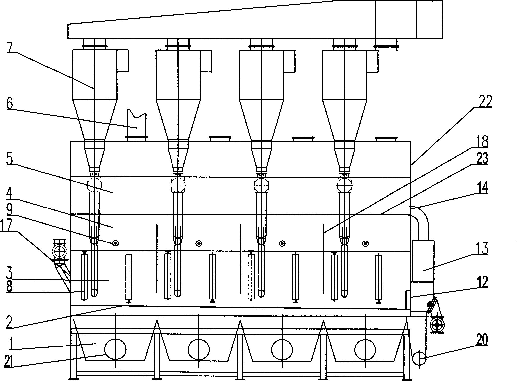
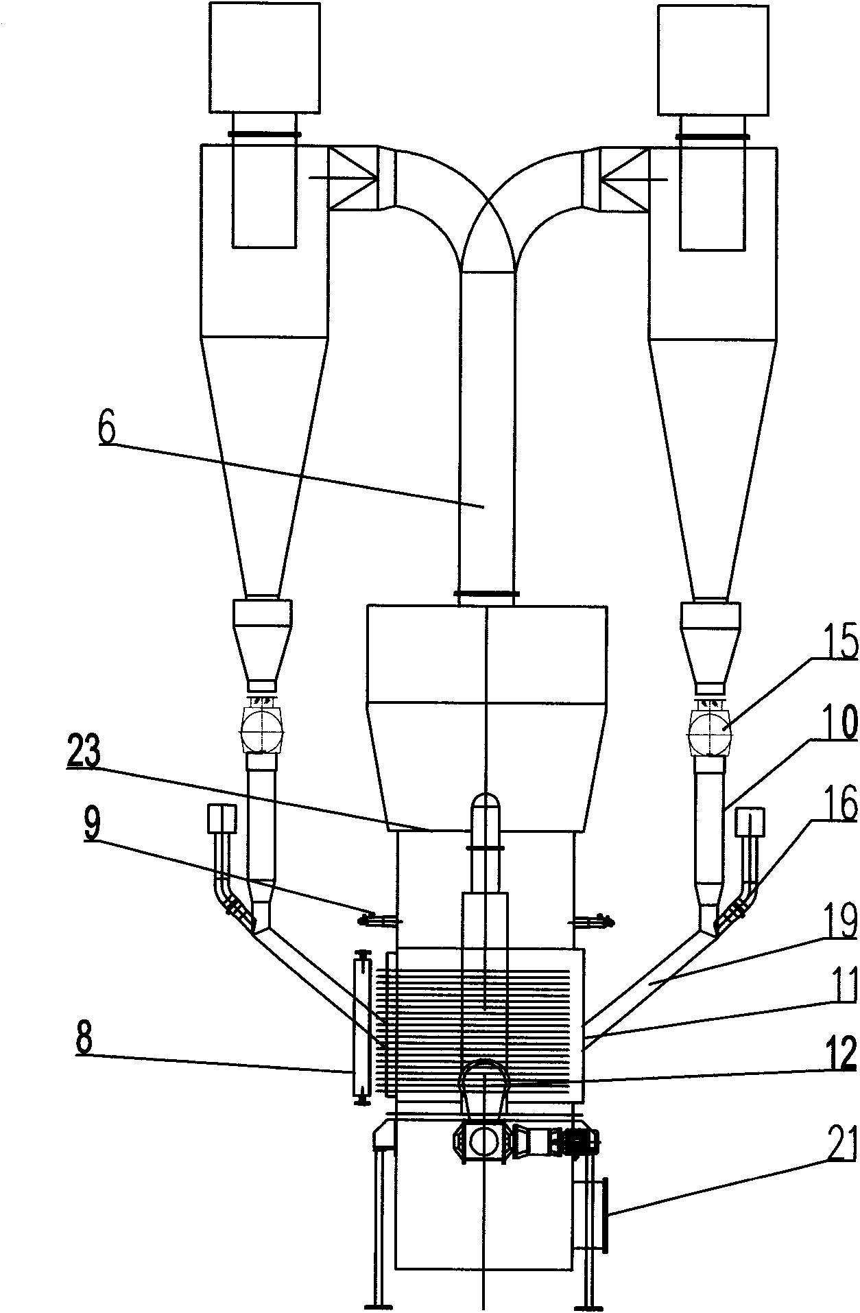
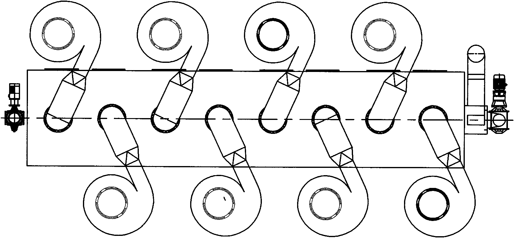
[0041] Such as Figures 1 to 5 As shown: the fluidized bed granulator is equipped with a nozzle 9 and a discharge port 12, and the main body of the fluidized bed is divided into air distribution chamber 1, air distribution screen plate 2, internal heating fluidization chamber 3, and spraying chamber from bottom to top. Fluidization chamber 4, separation chamber 5, a plurality of dust discharge pipes 6 are arranged on the top of the bed body, and a cyclone separator 7 is arranged outside the main body of the fluidized bed. A tube-and-tube heat exchanger 8 is arranged in the inner heating fluidization chamber 3, a nozzle 9 is installed on the side of the spray fluidization chamber 4, a vertical partition 18 is arranged in the fluidization chamber, and a return port 11 is provided The sides of the fluidized chamber 3 are heated internally, and are not higher than the horizontal line where the nearest nozzle 9 is located. The main engine of the fluidized bed communicates with the w...


PUM

PropertyMeasurementUnit
Heightaaaaaaaaaa

Abstract

The invention discloses a fluidized bed granulator, which relates to a device for grouting, granulating and drying crystal seeds. The fluidized bed granulator is provided with a nozzle and a discharge hole; the fluidized bed granulator is provided with an air distribution chamber, an air distribution net plate, an inner heating fluidizing chamber, a spray fluidizing chamber and a separation chamber in turn from the bottom to the top; the top of a bed body is provided with a dust discharge pipe, and the exterior of the bed body is provided with cyclone; the inner heating fluidizing chamber is provided with an inner heat exchanger; the nozzle is arranged in the spray fluidizing chamber or the separation chamber; the dust discharge pipe is connected with a cyclone inlet; the cyclone is communicated with a return port through a return upper section and a return lower section at the lower part in turn; and the return port is formed on the lateral surface of the fluidizing chamber and is not higher than the closest nozzle. The fluidized bed granulator does not produce large balls during working, can keep most material in the bed body and does not need to detach the nozzle during start and stop, can work in a small gas-liquid ratio without the interference of the nozzle and the discharge hole, increases the utilization rate of heat, and reduces the running cost.

Description

technical field [0001] The invention relates to a device for spraying granulation and drying crystal seeds, in particular to a continuous fluidized bed spraying granulation device. Background technique [0002] In the prior art, the fluidized bed granulator device for spraying granulation and drying of the seed crystals is often used to spray one or more liquid raw materials into a granular material containing substantially more than the granules to be produced. fluidized bed of small solid particles, evaporation of volatile constituents of one or more feedstocks which are sprayed in, supply of seeds to the fluidized bed or / and generation of seeds in the fluidized bed, and from The fluidized bed discharges granular matter. [0003] The normal structure of this type of fluidized bed granulator is that the fluidized bed has several unit fluidization chambers and several separation chambers, and the separation chambers are arranged one by one above the unit fluidization chambe...

Claims


Application Information

Patent Timeline
IPC IPC(8): B01J2/16
Inventor 王新月
Owner 王新月
Why Eureka
Try Eureka