Variable cross-section standing wave ultrasonic reactor

A technology of ultrasonic reactor and cross-section, which is applied in the direction of chemical/physical/physicochemical processes of energy application, and can solve the problems of low utilization rate of acoustic energy and uneven acoustic treatment, etc.

Inactive Publication Date: 2010-09-15
NANJING UNIV OF AERONAUTICS & ASTRONAUTICS
View PDF3 Cites 4 Cited by
  • Summary
  • Abstract
  • Description
  • Claims
  • Application Information

AI Technical Summary

Problems solved by technology

[0003] In order to overcome the problems of uneven sonication and low utilization rate of sound energy in existing ultrasonic reactors, the patent of the present invention provides a new ultrasonic reactor, which uses

Method used


Image

  • Variable cross-section standing wave ultrasonic reactor
  • Variable cross-section standing wave ultrasonic reactor
  • Variable cross-section standing wave ultrasonic reactor

Examples


Embodiment 1

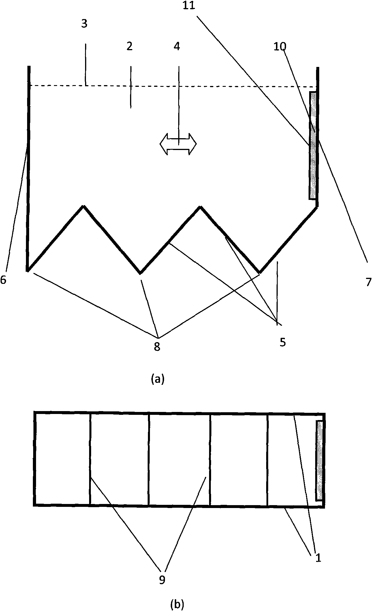
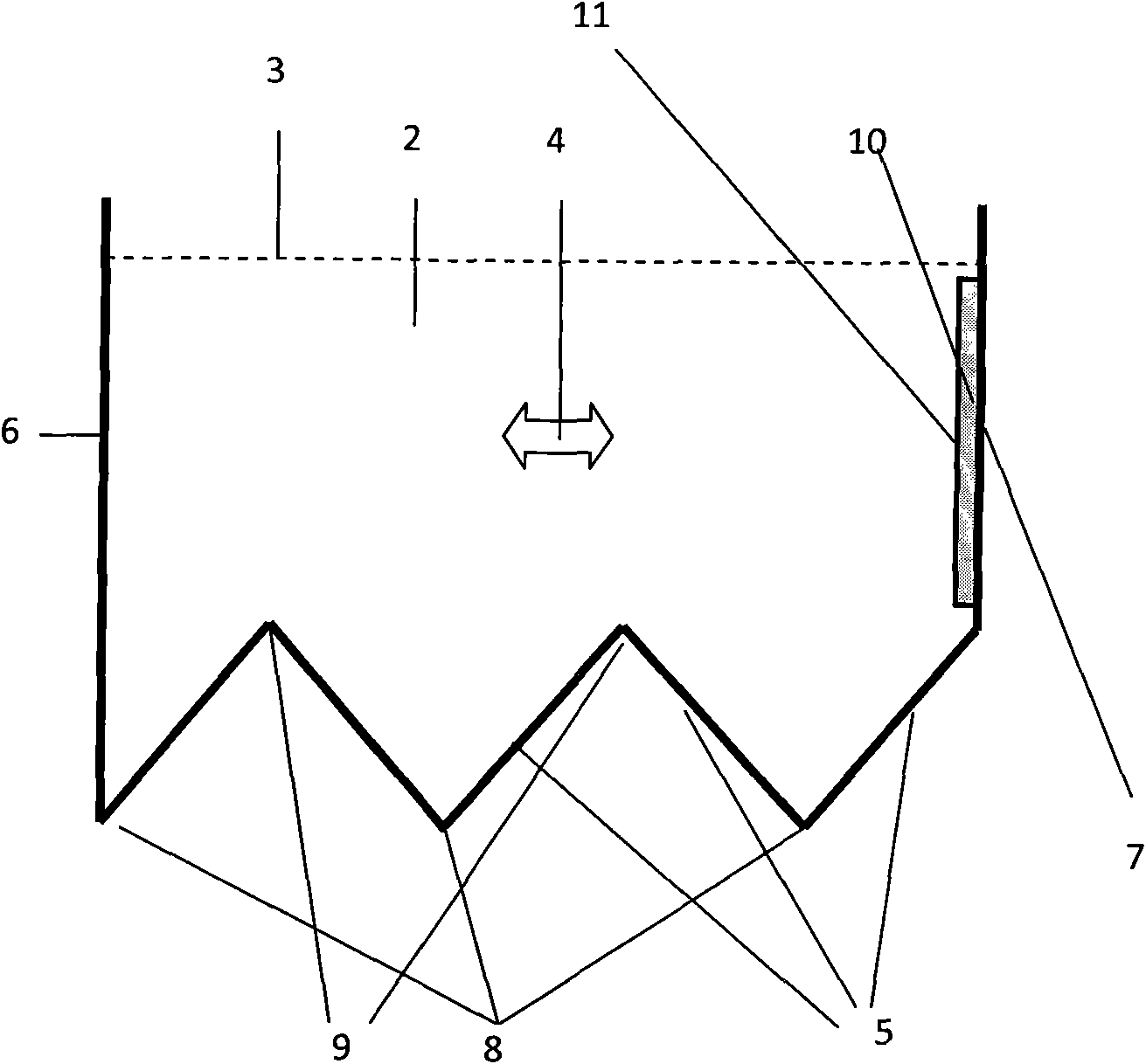
[0016] The variable cross-section standing wave ultrasonic reactor of embodiment one is as figure 1 shown.

[0017] The ultrasonic reactor rectangular metal box with a curved flat bottom is filled with treated water 2 . The ultrasonic transducer 10 is an immersion-type flat-panel ultrasonic transducer, which is fixed on the second wall 7 of the box. The distance between the acoustic radiation surface 11 and the opposite reflective wall surface, that is, the first wall surface 6, is an odd multiple of a quarter wavelength, so there is a gap between the acoustic radiation surface 11 and the first wall surface 6 when the acoustic reactor works. Standing wave sound field.

[0018] The size of the immersed flat panel ultrasonic transducer is 30cm (height)×12cm (width)×1cm (thickness), the working frequency f is 20kHz, and the working voltage is 65Vrms. The length of the rectangular metal box is 10.375cm, and the width is 13cm. The distance h between the bottom surface of the cu...

Embodiment 2

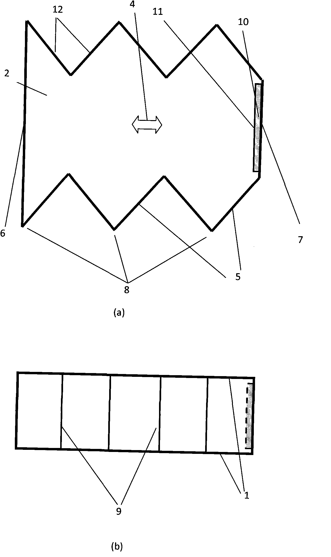
[0020] The variable cross-section standing wave ultrasonic reactor of embodiment two is as figure 2 shown.

[0021] The ultrasonic reactor rectangular metal box with a curved flat bottom surface and a curved flat top surface is filled with treated water. The submerged flat-panel ultrasonic transducer is fixed on the second wall 7 of the box. The distance between the acoustic radiation surface 11 and the opposite reflective wall surface, that is, the first wall surface 6, is an odd multiple of a quarter wavelength, so there is a standing wave between the acoustic radiation surface and the reflective wall surface when the acoustic reactor is working. sound field.

[0022] The size of the immersed flat panel ultrasonic transducer is 30cm (height)×12cm (width)×1cm (thickness), the working frequency f is 20kHz, and the working voltage is 65Vrms. The length of the rectangular metal box is 10.375cm, and the width is 13cm. The distance h between the bottom surface and the top sur...


PUM


Abstract

The invention relates to a variable cross-section standing wave ultrasonic reactor which relates to a device for processing a liquid by utilizing an ultrasonic cavitation effect. The variable cross-section standing wave ultrasonic reactor comprises a box body, at least one ultrasonic transducer (10) and an ultrasonic transducer driving circuit, wherein the box body is used for containing the processed liquid. The cross-sectional area of a standing wave sound field in the box body periodically changes along with the position of a cross section, and the cross section of the sound field is minimum at the position (a sound pressure nodal surface) where a sound pressure amplitude is zero; the cross section of the sound field is maximum at the position (a sound pressure antinodal surface) where the sound pressure amplitude is maximum; and the cross section of the sound field is linearly or nonlinearly transited from the minimum to the maximum between the adjacent sound pressure nodal and antinodal surfaces. The volume of the liquid near the sound pressure antinodal surface is increased and the volume of the liquid near the sound pressure nodal surface is decreased to improve the utilization ratio of the sound field energy of the ultrasonic reactor.

Description

technical field [0001] The variable cross-section standing wave ultrasonic reactor of the present invention relates to a device for treating liquid by using ultrasonic cavitation effect. Background technique [0002] The ultrasonic reactor uses the local high temperature and high pressure (~5000K, ~2000atm) generated by the ultrasonic cavitation effect to treat liquids such as water. Structurally, the ultrasonic reactor system includes a tank, the liquid to be processed in the tank, an ultrasonic transducer for applying ultrasonic waves to the liquid to be processed, and a drive circuit for the ultrasonic transducer. It is used in disinfection and sterilization of drinking water, decomposition of carcinogens in drinking water, disinfection and sterilization of wastewater, decomposition of organic matter in wastewater, physical catalysis of chemical synthesis and crystallization process, acceleration of fermentation process, production of biomass gas and liquid fuel, etc. It...

Claims


Application Information

Patent Timeline
IPC IPC(8): B01J19/10
Inventor 胡俊辉赵淳生
Owner NANJING UNIV OF AERONAUTICS & ASTRONAUTICS
Why Eureka
Try Eureka