
Cutting-free forming die of expansion anchor bolt

A technology for forming molds and pulling and blasting bolts, which is applied to bolts, manufacturing tools, threaded fasteners, etc., can solve problems such as the decline of physical properties of turning parts, the easy breaking of the head, and the difficulty in ensuring the quality of pulling and blasting bolts. Conducive to mass production, dense organization and high strength

Active Publication Date: 2010-09-15
EAGLE METALWARE
View PDF7 Cites 26 Cited by
  • Summary
  • Abstract
  • Description
  • Claims
  • Application Information

AI Technical Summary

Problems solved by technology

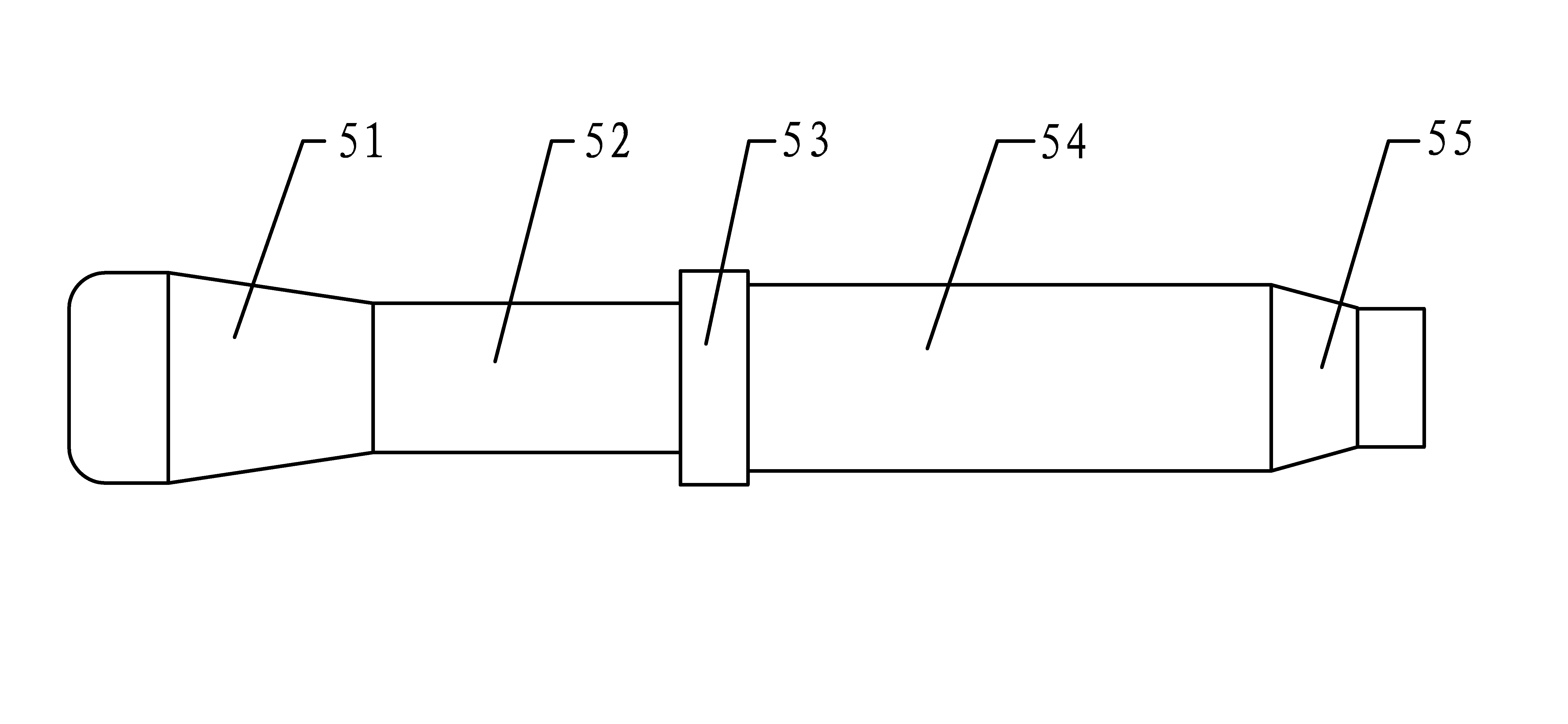
[0004] Due to the stress characteristics of the blasting bolts, the blasting bolts are required to have higher rigidity, strength and shear resistance. However, most of the existing blasting bolts are formed by turning, because the turning process is to remove part of the material on the surface of the ingredients. In order to achieve the purpose of forming, the physical properties of the turning parts decrease during the processing process. During use, damage such as breaking and shearing often occurs in these turning parts; therefore, in order to improve performance, there is also a process of using cold heading to form detonation bolts. , but the existing cold heading forming process is often used to form the rod part. Since the diameter of the sleeve cylinder 52 is smaller than the diameter of the support step 53 and the cone bottom diameter of the cone 51, the head is a structure with a thin center and thick ends. The diameter of the sleeve cylinder 52 is generally smaller than the diameter of the rod, and it is difficult to form it by cold heading. Therefore, the turning process is generally used when processing the head, which is difficult to ensure the quality of the detonation bolt. break

Method used


Image

  • Cutting-free forming die of expansion anchor bolt
  • Cutting-free forming die of expansion anchor bolt
  • Cutting-free forming die of expansion anchor bolt

Examples


Embodiment Construction

[0050] Below in conjunction with accompanying drawing, the present invention will be further described, see Figure 1 to Figure 10As shown, this is a preferred embodiment of the present invention.

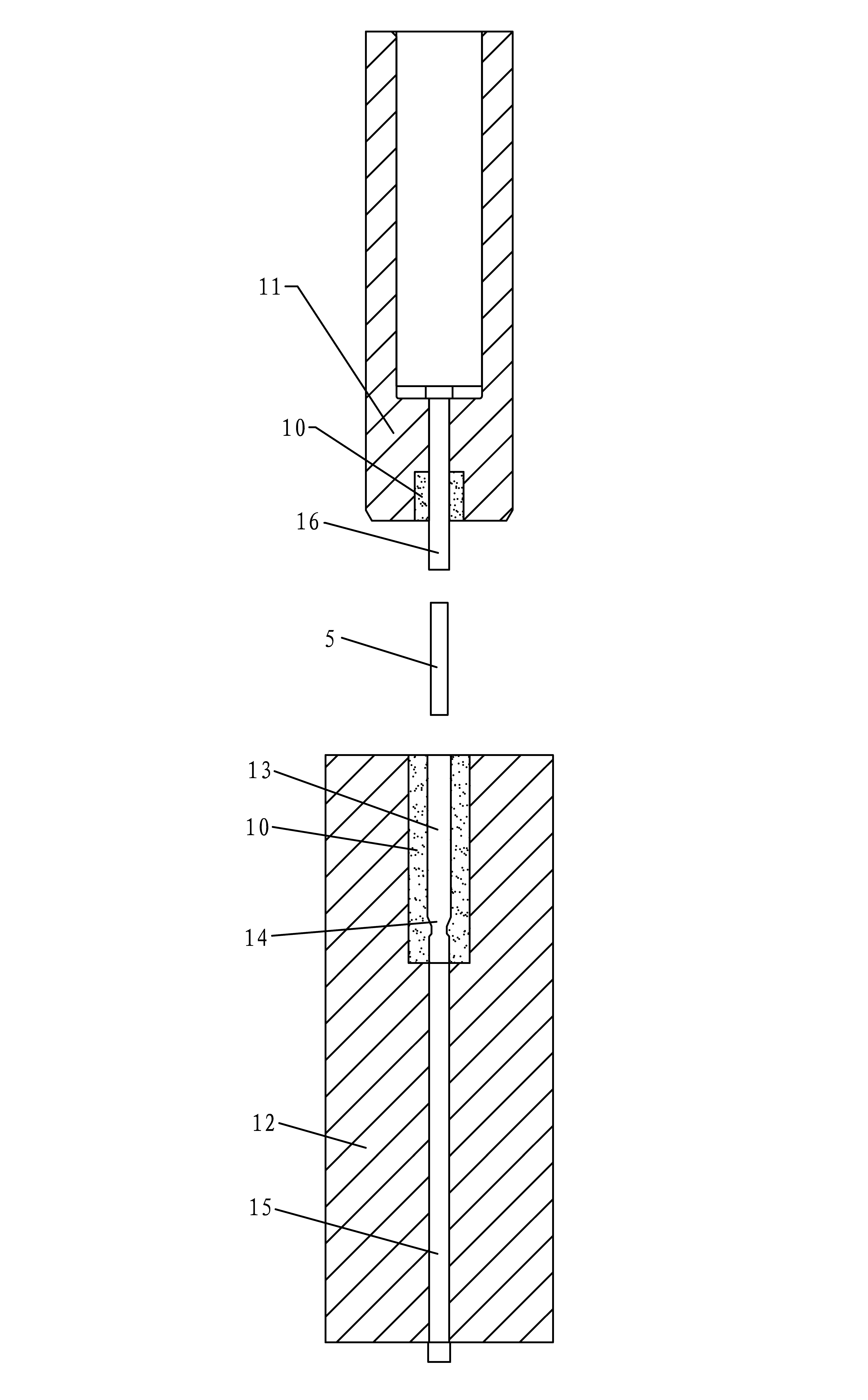
[0051] A cutting-free forming die for a bursting bolt, which sequentially includes a forming die for a first station, a forming die for a second station, a forming die for a third station, and a forming die for a fourth station; the forming die for the first station Including the first station male mold 11 and the first station female mold 12, the first station female mold 12 includes a first mold core 13, and the tail of the first mold core 13 is provided with a knocking table molding cavity 14, The tail of the first mold core 13 is connected with a push rod 15 that can slide axially along the first mold core 13, and the male mold 11 of the first station is protruded with a first mold core 13 that matches the opening end. A punch 16; the second station forming mold includes a sec...


PUM


Abstract

The invention discloses a cutting-free forming die of an expansion anchor bolt, which comprises a first station forming die, a second station forming die, a third station forming die and a fourth station forming die in turn, wherein the first station forming die is provided with a knocking platform forming cavity; the second station forming die is provided with a supporting step tail part forming cavity; the third station forming die is provided with a supporting step forming cavity; the fourth station forming die is provided with a taper hole; and a cone forming internal mold is movably sleeved in the taper hole and comprises at least three movable molds which are separated from one another. A blank is processed by cold heading extension bar parts of the first station forming die, the second station forming die and the third station forming die in turn, and then is formed into the head part of the expansion anchor bolt by the movable molds of the fourth station forming die; the formed expansion anchor bolt is not processed by turning, and because the cold heading makes the expansion anchor bolt have the advantages of compact texture, high strength, high tensile property and shear resistance, good product quality and high processing efficiency, and is favorable for large-scale production of the expansion anchor bolt.

Description

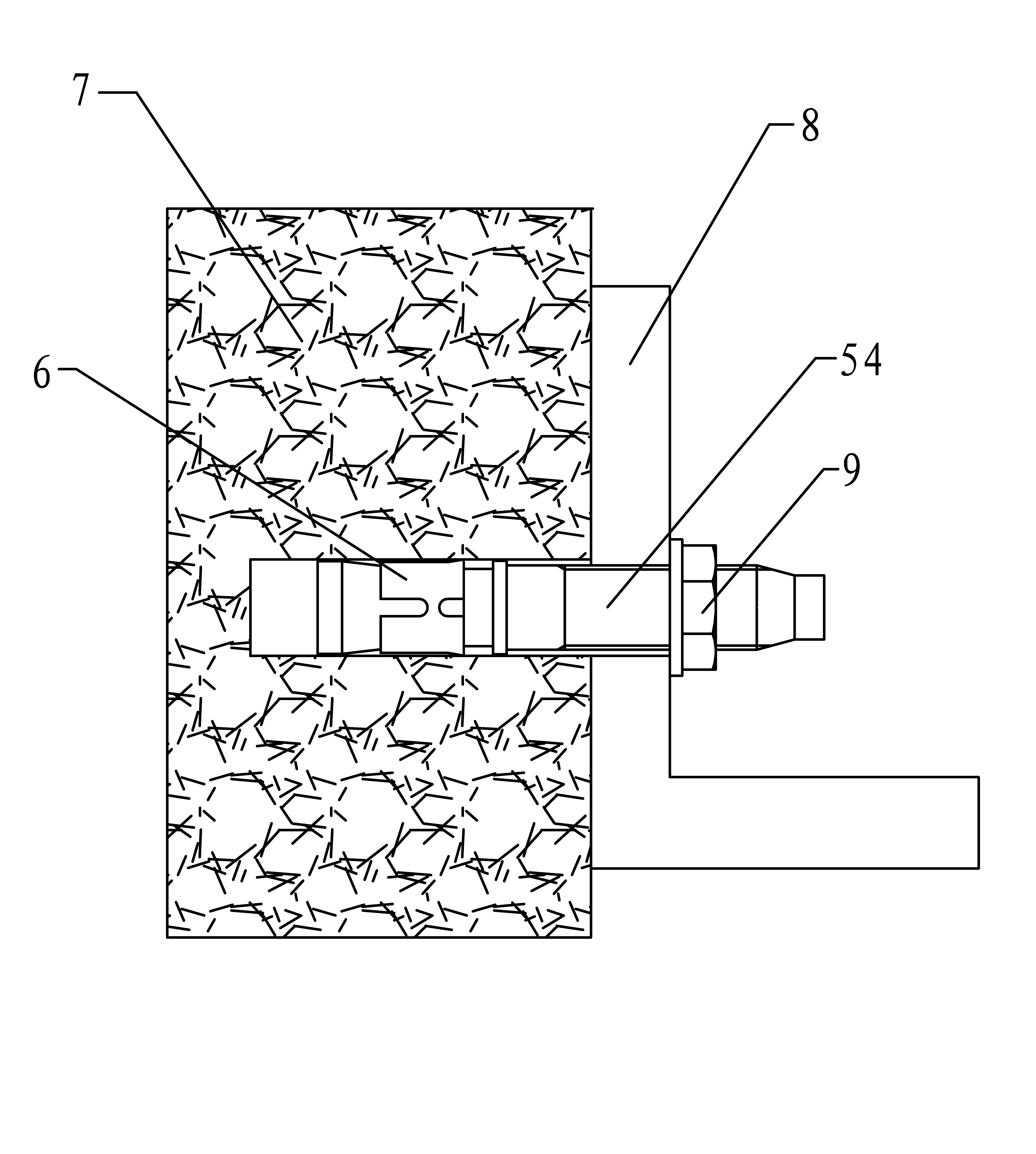
technical field [0001] The invention relates to the technical field of forming dies for blasting bolts, in particular to a cutting-free forming die for blasting bolts. Background technique [0002] Pull bolts are widely used in modern building curtain walls, building decoration, electromechanical installation and other occasions to fasten objects to fixed objects. Explosion bolts have the characteristics of large load, wide application and convenient installation. They can replace anchor bolts, cancel embedded parts, improve installation efficiency and accuracy, and are more widely used in subway installation, building installation, power supply installation, and highway installation. more and more widely. [0003] See figure 1 and figure 2 As shown, the pull bolt is generally composed of a head and a shaft. The head includes a cone 51 and a casing cylinder 52 . During use, the head is inserted into the installation hole provided by the fixture 7, the casing cylinder 52...

Claims


Application Information

Patent Timeline
Patent Type & Authority Applications(China)
IPC IPC(8): B21J13/02B21K1/44
Inventor 王友良
Owner EAGLE METALWARE
Learn More