Ball distribution mechanism of steel ball processor

A technology of processing machine and ball separation, which is applied in metal processing, manufacturing tools, conveyor objects, etc., can solve the problems of large size of ball separation mechanism, large power transmission loss, unfavorable energy saving, etc., and achieves reduction of transmission links and energy saving. , the effect of avoiding transmission loss

Active Publication Date: 2010-09-15
CHANGSHU FEIFAN METALWORK
View PDF8 Cites 12 Cited by
  • Summary
  • Abstract
  • Description
  • Claims
  • Application Information

AI Technical Summary

Problems solved by technology

But the ball distribution mechanism that introduces in the above-mentioned patent application scheme has following shortcoming: the one, the power transmission loss is big, is unfavorable for saving energy, because the power of the ball distribution mechanism comes from the screw rod of the quenching groove of quenching mechanism, due to the speed of motion of the screw rod Far greater than the moving speed of the ball distribution plate of the ball distribution mechanism, so the ball distribution mechanism is equipped with a reducer, a sprocket is fixed on the screw rod, and a sprocket is also fixed on the power input shaft of the reducer to distribute the ball. The disk is fixed on the power output shaft of the reducer, and the aforementioned pair of sprockets are connected by a chain.
When the screw rod is in motion, the sprocket fixed on the screw rod drives the sprocket fixed on the power input shaft of the reducer through the chain, and the ball distribution disc works after deceleration; The phenomenon of the ball, because the ball distribution mechanism is connected with the screw rod of the quenching tank of the quenching mechanism, so when the screw rod of the quenching mechanism stops moving, the ball distribution plate of the ball distribution mechanism also stops moving, so it is still in the distribution mechanism. The steel balls to be quenched in the upwardly facing middle ball storage cavity of the ball plate cannot be introduced into the quenching tank, resulting in waste, unless they are quenched when the next quenching mechanism is working after returning to the furnace, that is to say, the quenching mechanism stops working every time. There are at least 3-4 steel balls staying in the ball distributing plate (as shown in Fig. 3 of CN101177726A and shown in Fig. 4 of CN101177727A for details) and cannot enter the quenching tank for quenching; the third is because the ball distributing mechanism needs to be equipped with a speed reducer, As a result, the volume of the ball distribution mechanism is huge

Method used


Image

  • Ball distribution mechanism of steel ball processor
  • Ball distribution mechanism of steel ball processor

Examples


Embodiment Construction

[0016] In order to enable the examiners of the patent office, especially the public, to understand the technical essence and beneficial effects of the present invention more clearly, the applicant will describe in detail below in conjunction with the accompanying drawings in the form of embodiments, but none of the descriptions of the embodiments is a description of the present invention. Restriction of the inventive solution, any equivalent transformation made according to the concept of the present invention which is only in form but not in substance shall be regarded as the scope of the technical solution of the present invention.

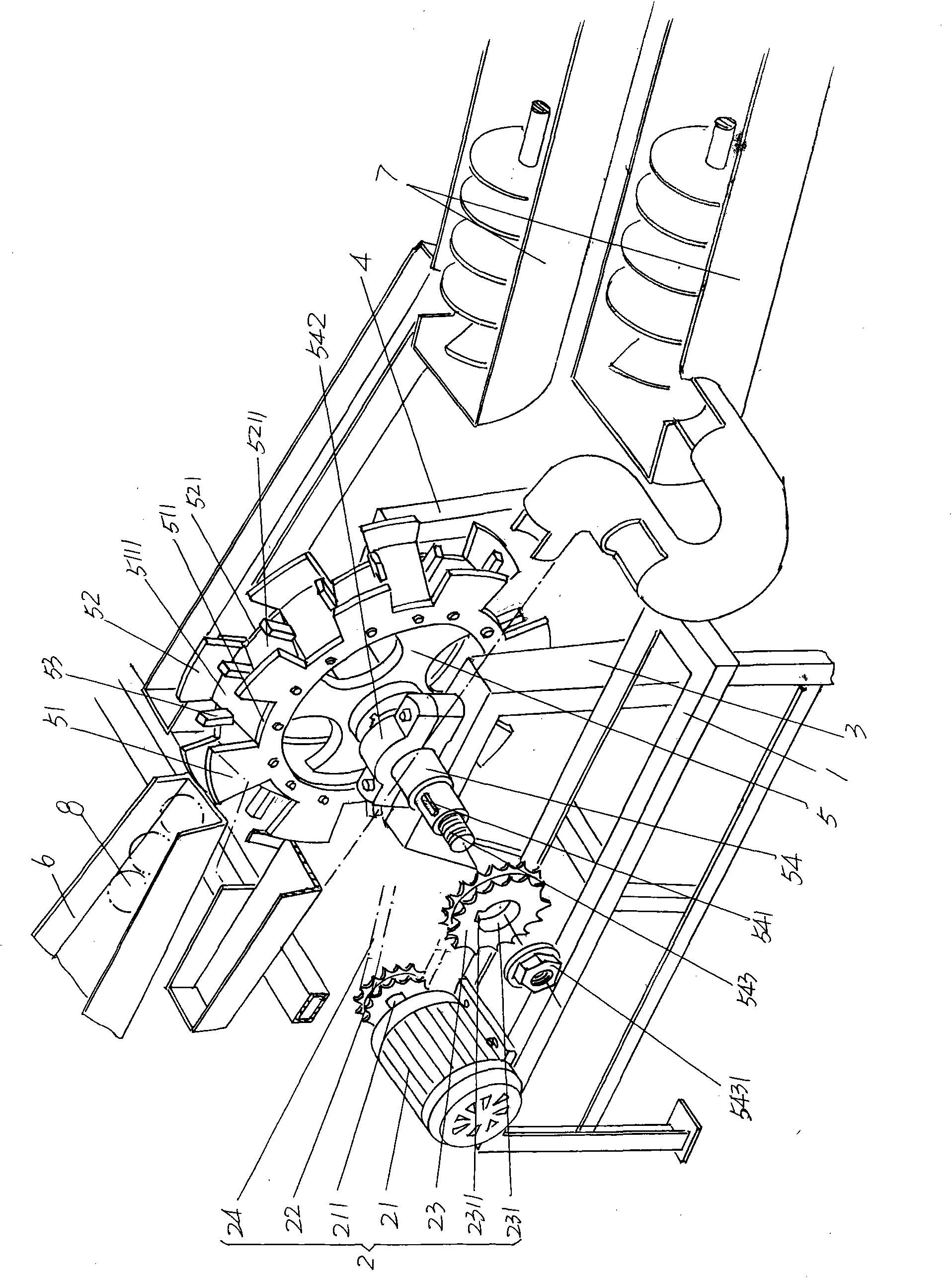
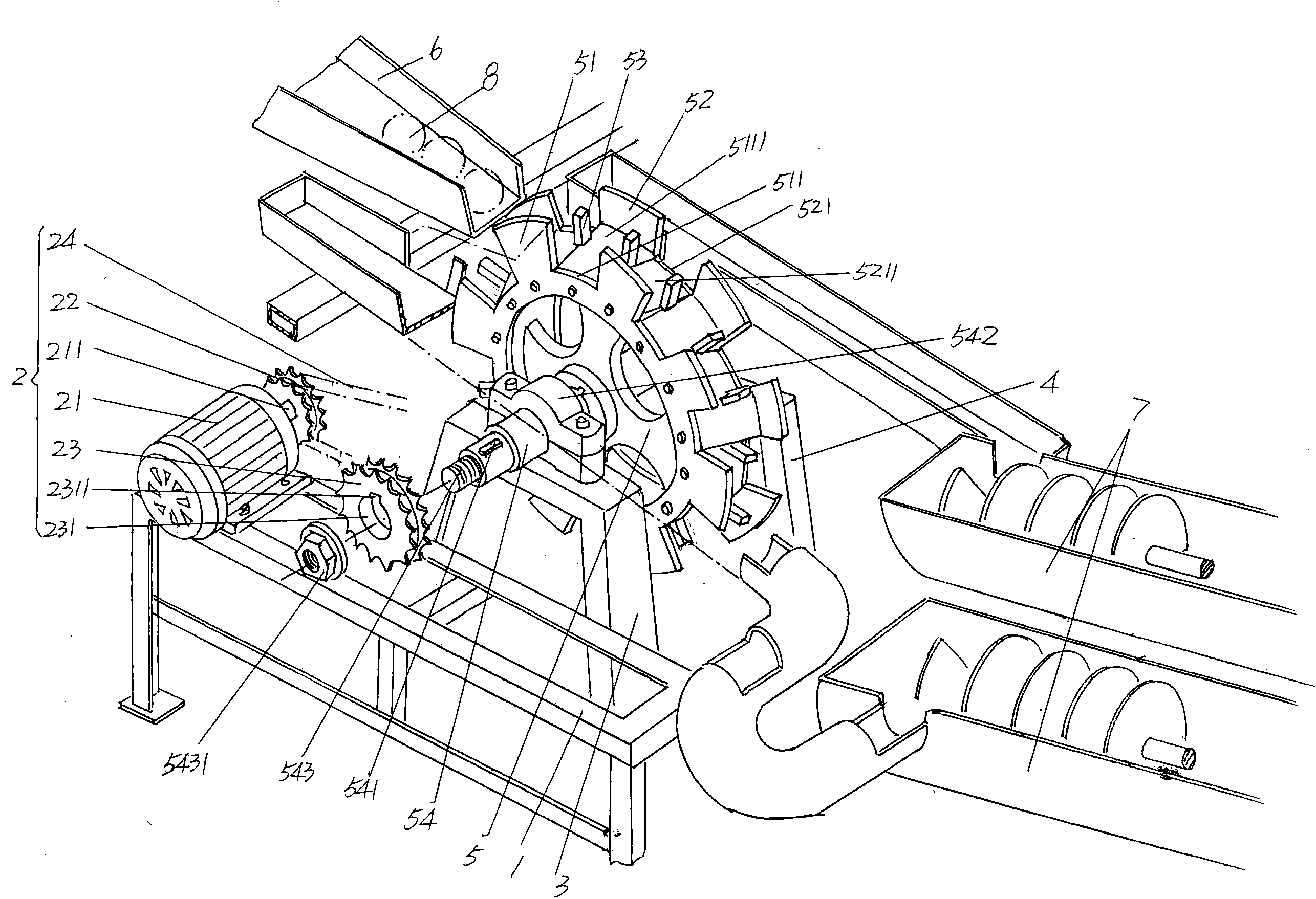
[0017] please see figure 1 , in the figure, the rolling steel ball discharge guide groove 6 and the quenching groove 7 as the steel ball processing machine are provided, wherein, the quenching groove 7 has a pair, and the ball distribution mechanism provided by the present invention is located at the rolling steel ball discharge Between the guid...


PUM


Abstract

The invention relates to a ball distribution mechanism of a steel ball processor, belonging to the technical field of steel ball processing machinery. The ball distribution mechanism of a steel ball processor comprises a stand, a power transmission device arranged on the stand, a first ball distribution disc support, a second ball distribution disc support and a ball distribution disc, wherein the first ball distribution disc support and the second ball distribution disc support are mutually parallel, the ball distribution disc is arranged on the first ball distribution disc support and the second ball distribution disc support and connected with the power transmission device, one side of the disc edge of the ball distribution disc is provided with first ball blocking plates, a first ball outlet is formed between the two adjacent first ball blocking plates, the other side of the disc edge of the ball distribution disc is provided with second ball blocking plates, a second ball outlet is formed between the two adjacent second ball blocking plates, an area from the first ball outlet to the second ball blocking plates is a first ball storage cavity, an area from the second ball outlet to the first ball blocking plates is a second ball storage cavity, and the first ball storage cavity and the second ball storage cavity are separated by a blocking bulge. The invention can reduce transmission links and avoid transmission loss, has no phenomenon that steel balls to be quenched are left in the ball distribution disc, has simple integral structure and saves manufacturing cost and installation space.

Description

technical field [0001] The invention belongs to the technical field of steel ball processing machines, and in particular relates to a ball distributing mechanism of a steel ball processing machine. Background technique [0002] The ball dividing mechanism of the steel ball processing machine is also called the ball feeding mechanism of the steel ball processing machine. When there is more than one quenching groove in the quenching mechanism of the steel ball processing machine, the ball dividing mechanism will come from the ball rolling mechanism and roll The steel balls introduced into the raceway are alternately distributed to each quenching tank for quenching. [0003] In the technical scheme of the quenching mechanism of the steel ball quenching machine that CN101177726A provides and the steel ball quenching machine that CN101177727A recommends in the invention patent application publication number, all relate to a ball-distributing mechanism (both patent applications ar...

Claims


Application Information

Patent Timeline
Patent Type & Authority Applications(China)
IPC IPC(8): B23Q7/00B23P23/02C21D9/36C21D1/62B65G47/88
Inventor 陈刚
Owner CHANGSHU FEIFAN METALWORK
Why Eureka
Try Eureka