
Hydropower station bank slope energy dissipation structure

A hydropower station and energy dissipation technology, which is applied in water conservancy projects, coastline protection, sea area engineering, etc., can solve problems such as large earthwork excavation and concrete volume, insufficient space for building layout, large tailwater fluctuations and atomization, etc. Achieve the effects of small engineering volume, good dispersion of water flow, and reduction of engineering excavation

Inactive Publication Date: 2011-07-20
CHONGQING JIAOTONG UNIVERSITY
View PDF0 Cites 0 Cited by
  • Summary
  • Abstract
  • Description
  • Claims
  • Application Information

AI Technical Summary

Problems solved by technology

Although the deflected flow energy dissipation has the advantages of simple structure, can effectively control the position, range and flow distribution of the jet falling into the downstream river bed, has strong adaptability to tailwater variable amplitude, and has the advantages of small engineering quantity, it has become the most widely used energy dissipation structure in engineering. , but in engineering practice it also has the following disadvantages: the downstream local erosion problem is more serious, there are more accumulations, and the tail water fluctuation and atomization are relatively large
The method of artificially building stilling pools for energy dissipation often has the advantages of stable flow, good energy dissipation effect, strong adaptability to geological conditions and tailwater amplitude change, and small water atomization. However, building hydropower stations in mountainous rivers During the project, according to the aforementioned characteristics of mountainous rivers, there are often problems such as long building aprons, insufficient space for building layout, large excavation volume of earthwork and concrete volume, and high project cost.

Method used


Image

  • Hydropower station bank slope energy dissipation structure
  • Hydropower station bank slope energy dissipation structure
  • Hydropower station bank slope energy dissipation structure

Examples


Embodiment Construction

[0029] The present invention will be further described in detail below in conjunction with the accompanying drawings and specific embodiments.

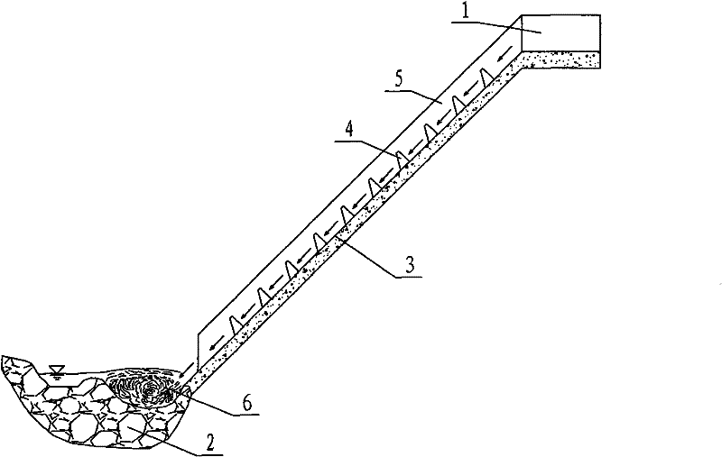
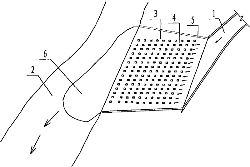
[0030] In specific implementation, such as figure 1 and figure 2 As shown, a bank slope energy dissipation structure of a hydropower station has a structure including a spillway chute outlet section 1 whose width of the cross section gradually increases, and an outlet section 1 of the dam spillway and a riverbed 2 downstream of the dam obliquely arranged The energy-dissipating bank slope 3 between them is fixedly provided with several rows of energy-dissipating piers 4 on the energy-dissipating bank slope 3 . The width of the outlet section 1 of the spillway chute is gradually widened to reduce the single-width flow; the slope of the energy dissipation bank 3 is 60°; the stilling piers 4 are neatly arranged horizontally and vertically set in rows; the horizontal spacing of the stilling pier 4 is 3 to 4 times the transverse width of...


PUM


Abstract

The invention discloses a hydropower station bank slope energy dissipation structure, which comprises an exit section, of which the width of the flow cross-section is increased gradually, of a spillway chute, and an energy dissipation bank slope which is obliquely built between the exit section of the spillway chute of a dam, wherein a plurality of rows of energy dissipation pillars are built on the energy dissipation bank slop. According to the technical scheme, the width of the flow cross-section of the exit section of the spillway chute is increased gradually to effectively reduce unit discharge of a water flow; on the energy dissipation bank slope, the water flow hits the energy dissipation pillars constantly and is mixed with the air to dissipate a small part of energy; a high-speed water flow, after flowing by the energy dissipation bank slope, hits the river bed at the bottom of the bank slope at a certain incoming water angle and washes a local scour pit at the position of theriver bed at the bottom of the bank slope; and the water flow generates a big vortex in the scour pit, so a large part of energy is dissipated under the high turbulent fluctuation shearing action of the vortex. The energy dissipation structure is built with small engineering excavated volume and at low cost, is simple and compact, ensures light washing of the bank slope and downstream riverway and little accretion, and has the advantage of high energy dissipation effect.

Description

technical field [0001] The invention relates to the field of hydraulic engineering, in particular to a bank slope energy dissipation structure of a hydropower station. Background technique [0002] The energy dissipation structure is a kind of kinetic energy that eliminates the rapid discharge of the drainage structure, prevents or reduces the erosion and damage of the water flow to the hydraulic structure and the downstream canal, etc., and makes the water flow and the downstream normal water flow in a short distance. Convergence and construction of engineering facilities. [0003] At present, with the gradual development of hydropower resources in mountainous rivers in my country, the development of hydropower engineering construction in China has entered a climax stage, especially in the western mountainous areas where a large number of small and medium hydropower stations have been built. The water flow in natural rivers is generally slow flow, and the single-width disc...

Claims


Application Information

Patent Timeline
Patent Type & Authority Patents(China)
IPC IPC(8): E02B8/06
Inventor 杨胜发付旭辉胡鹏飞金龙许俊杰刘汉天
Owner CHONGQING JIAOTONG UNIVERSITY
Learn More