
Method for cooling air film of turbine blade of aircraft engine

A technology for aero-engines and turbine blades, applied in the cooling of engines, cooling of turbines/propulsion devices, engine components, etc., can solve the problem of increasing cooling efficiency, difficulty in making stepwise progress, and small room for improvement of air cooling technology, etc. problems, to achieve the effect of improved cooling efficiency, easy portability and storage, and reduced energy loss

Inactive Publication Date: 2010-09-15
INST OF ENGINEERING THERMOPHYSICS - CHINESE ACAD OF SCI
View PDF6 Cites 18 Cited by
  • Summary
  • Abstract
  • Description
  • Claims
  • Application Information

AI Technical Summary

Problems solved by technology

However, air cooling is a double-edged sword, and the cooling efficiency can never increase infinitely without increasing the cooling air flow
As the inlet temperature of the turbine increases, more high-pressure air needs to be drawn from the compressor, which is originally used to participate in combustion and perform work, which has an adverse effect on the specific work and cycle efficiency of the gas turbine, partially offsetting the improvement The efficiency gain brought by the gas temperature before the turbine has even developed to an unacceptable level, making the existing air film cooling mainly, including jet impingement cooling, fin turbulence cooling and column rib cooling, etc. The space for improvement of air cooling technology is getting smaller and smaller, and it is difficult to make stepwise progress

Method used


Image

  • Method for cooling air film of turbine blade of aircraft engine
  • Method for cooling air film of turbine blade of aircraft engine
  • Method for cooling air film of turbine blade of aircraft engine

Examples


Embodiment Construction

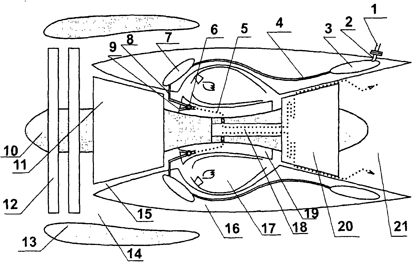
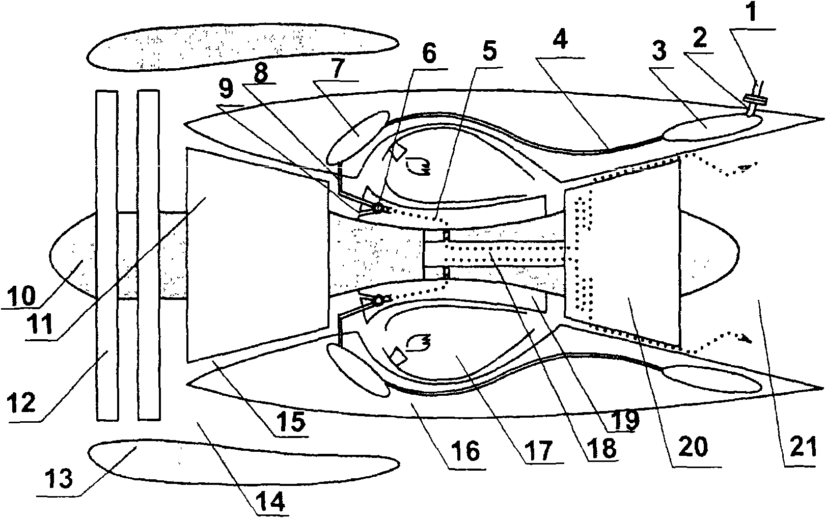
[0032] The technical scheme of the present invention uses solid working fluid as the source of cooling working medium, and the solid working medium is NH 4 HCO 3 , the cooling working fluid is its pyrolysis product, that is, NH with a volume ratio of 1:1:1 3 、H 2 O and CO 2 The mixed gas and the cooling working medium are efficiently transported from the source to the dedicated air supply channel for the cooling air of the turbine blades of the engine, and the air is replaced with the cooling working medium of the present invention, so that the film cooling method can be implemented.

[0033] The present invention can completely or partially replace air film cooling, and is applied to high-thrust and high-parameter aero turbine engines. When the amount of cooling air cannot be further increased and higher cooling efficiency must be achieved, the first-stage guide blade and the first-stage rotor blade Wait for the cooling of the aeroengine components with the highest thermal l...


PUM


Abstract

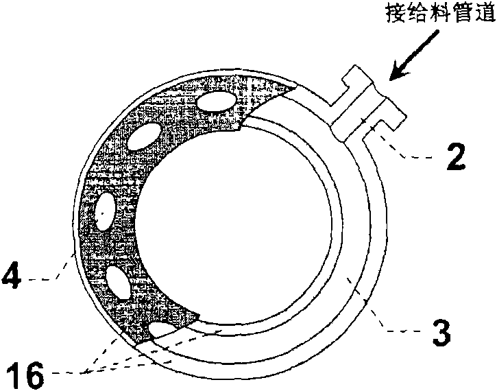
The invention discloses a method for cooling an air film of a turbine blade of an aircraft engine. In the cooling method, the solid working medium NH4HCO3 is used as the resource of the cooling working medium; an annular cavity disposed inside the external casing of the engine and outside the tailpipe of the engine is used as the back-heating cavity, and the solid working medium is input into theback-heating cavity. The solid working medium is heated and decomposed into the intermediate-temperature and high-pressure working medium by the waste heat of the tail gas of the engine; the cooling working medium is driven by the pressure to enter the original air supplying channel for cooling the air film via an air channel communicated with the outlet of the back-heating cavity and the coolingair inlet of the turbine blade, so that the air film is cooled by the turbine blade of the aircraft engine. The endothermic decomposition reaction occurs in the cooling course, so that the cooling efficiency is improved remarkably; and the cooling working medium is the thermal decomposition product. The invention can completely or partially replace the cooling of the air film and can cool the members having highest heat loads of the aircraft engine such as a first-stage guide blade and a first-stage rotor blade when the amount of the cooling air cannot be further increased and the higher cooling efficiency must be achieved.

Description

technical field [0001] The invention relates to an air film cooling method suitable for power turbine blades of a high-thrust high-performance aeroengine. Background technique [0002] Aviation power is a key science and technology to promote the development of national economy and national defense construction. The engine is called the "heart" of the aircraft, and the aeroengine is the core technology of the aviation industry, and it is also an important symbol to measure a country's military equipment level, technological and industrial strength and comprehensive national strength. According to an analysis by the Japanese industry, in terms of the value ratio created by unit weight, the value of ships is 1, that of cars is 9, that of computers is 300, that of regional aircraft is 800, and that of aeroengines is as high as 1,400. Flowers", "The Crown Jewels". [0003] The most widely used aero-engine in modern times is the aero-gas turbine engine. An important symbol of t...

Claims


Application Information

Patent Timeline
IPC IPC(8): F01D5/18F02C7/16
Inventor 梁世强雷兢淮秀兰
Owner INST OF ENGINEERING THERMOPHYSICS - CHINESE ACAD OF SCI
Learn More