
Self-preheating waste gas incinerator

An incinerator and self-preheating technology, applied in incinerators, combustion methods, combustion types, etc., can solve the problems of low heat recovery rate, insufficient waste gas incineration treatment, and low temperature in the incineration chamber, and achieve the effect of waste gas treatment. Good, reduce energy consumption, high efficiency of exhaust gas purification

Inactive Publication Date: 2010-09-15
ZHEJIANG HUALI INTELLIGENT EQUIP CO LTD
View PDF5 Cites 12 Cited by
  • Summary
  • Abstract
  • Description
  • Claims
  • Application Information

AI Technical Summary

Problems solved by technology

The incineration process will generate a large amount of heat while processing the waste gas. The waste gas incineration equipment will be equipped with some heat energy recovery devices. At present, the common heat energy recovery device of the waste gas incineration equipment is to pass the high-temperature gas after incineration through a hot water tank, and use heating Water is used to recover heat energy. The biggest disadvantage of this recovery method is that the recovery rate of heat energy is not high.
Part of the exhaust gas incineration treatment device directly enters the incineration chamber without preheating. A large amount of low-temperature exhaust gas entering the incineration chamber will cause the incineration room temperature to be too low and the exhaust gas incineration treatment is insufficient. Most of the exhaust gas incineration treatment devices are additionally preheated device, high energy consumption, large investment, complex structure

Method used


Image

  • Self-preheating waste gas incinerator
  • Self-preheating waste gas incinerator

Examples


Embodiment Construction

[0017] The present invention will be further described below with reference to the accompanying drawings.

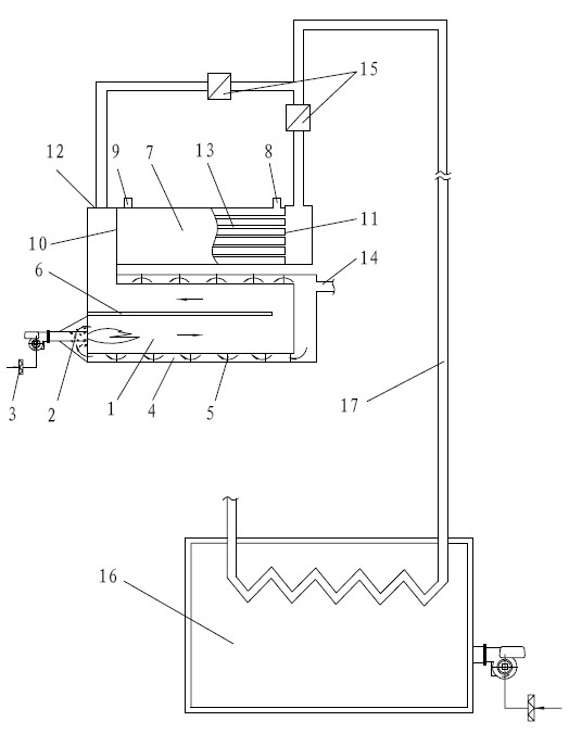
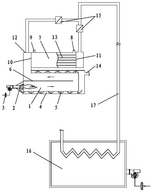
[0018] A self-preheating waste gas incinerator, such as figure 1 As shown, it includes an incineration chamber 1, the interior of the incineration chamber 1 is provided with a partition 6, the entrance of the incineration chamber 1 is connected with a preheating pipe 4, and the preheating pipe 4 is set outside the incineration chamber 1, A spoiler 5 is arranged inside the preheating pipe 4; a heat exchanger 7 is arranged at the outlet of the incineration chamber 1, and several heat exchange tubes 13 are arranged inside the heat exchanger 7, and the inside and the outside of the heat exchange tube 13 are mutually sealed , the outlets and inlets of the several heat exchange tubes 13 form the high-temperature outlet 11 and the high-temperature inlet 10 of the heat exchanger 7 respectively, and the heat exchanger 7 is also provided with a low-temperature outlet 9 and a low-t...


PUM


Abstract

The utility model discloses a self-preheating waste gas incinerator which comprises an incineration chamber. A diaphragm is arranged in the incineration chamber, the inlet of the incineration chamber is communicated with a preheating pipe, the preheating pipe is sleeved outside the incineration chamber, the outlet of the incineration chamber is communicated with a heat exchanger, and a gas exhaust hole is respectively arranged at the high temperature outlet and the high temperature inlet of the heat exchanger. The utility model has the advantages of reasonable design, simple structure, favorable waste gas treatment effect, high waste gas purification rate through actual detection, small utilization stroke for heat energy recovery and little heat energy loss, saves a set of independent preheating device through a spontaneous preheating structure design, reduces the energy consumption on the basis of ensuring the preheating effect, can more sufficiently decompose the waste gas after preheating, can secondarily recover the heat energy, greatly enhance the recovery efficiency and efficiently save the energy.

Description

technical field [0001] The invention relates to a waste gas treatment device, in particular to a self-preheating waste gas incinerator. Background technique [0002] Quite a lot of industrial production will produce waste gas, which is harmful to the human body and pollutes the atmosphere. Therefore, it is necessary to treat the waste gas into a harmless gas before allowing it to be discharged. A considerable amount of waste gas is a gaseous organic compound. The use of incineration technology is the best Common, effective, and lowest-cost exhaust gas treatment process. The incineration process will generate a lot of heat while processing the waste gas. The waste gas incineration equipment will be equipped with some heat energy recovery devices. At present, the heat energy recovery and utilization device of the common waste gas incineration equipment is to pass the high-temperature gas after incineration through a hot water tank, and use heating Water is used to recover hea...

Claims


Application Information

Patent Timeline
Patent Type & Authority Applications(China)
IPC IPC(8): F23G7/06
Inventor 吕建立吴海珍
Owner ZHEJIANG HUALI INTELLIGENT EQUIP CO LTD
Learn More