System and array for tracking solar energy linearly

A tracking system and solar energy technology, which are applied in the field of linear tracking where the focus of solar energy tracking is a straight line, and the field of forming an array of tracking and its utilization, can solve the problem of non-movement of the focal line, and achieve the effect of overcoming the small load and expanding the technology and scope.

Inactive Publication Date: 2010-09-15
BEIJING WISWORD HI TECH
View PDF3 Cites 14 Cited by
  • Summary
  • Abstract
  • Description
  • Claims
  • Application Information

AI Technical Summary

Problems solved by technology

It solves the tracking problem that the focal line does not move when the trough type one-way tracking is used in the prior art

Method used


Image

  • System and array for tracking solar energy linearly
  • System and array for tracking solar energy linearly
  • System and array for tracking solar energy linearly

Examples


Embodiment 1

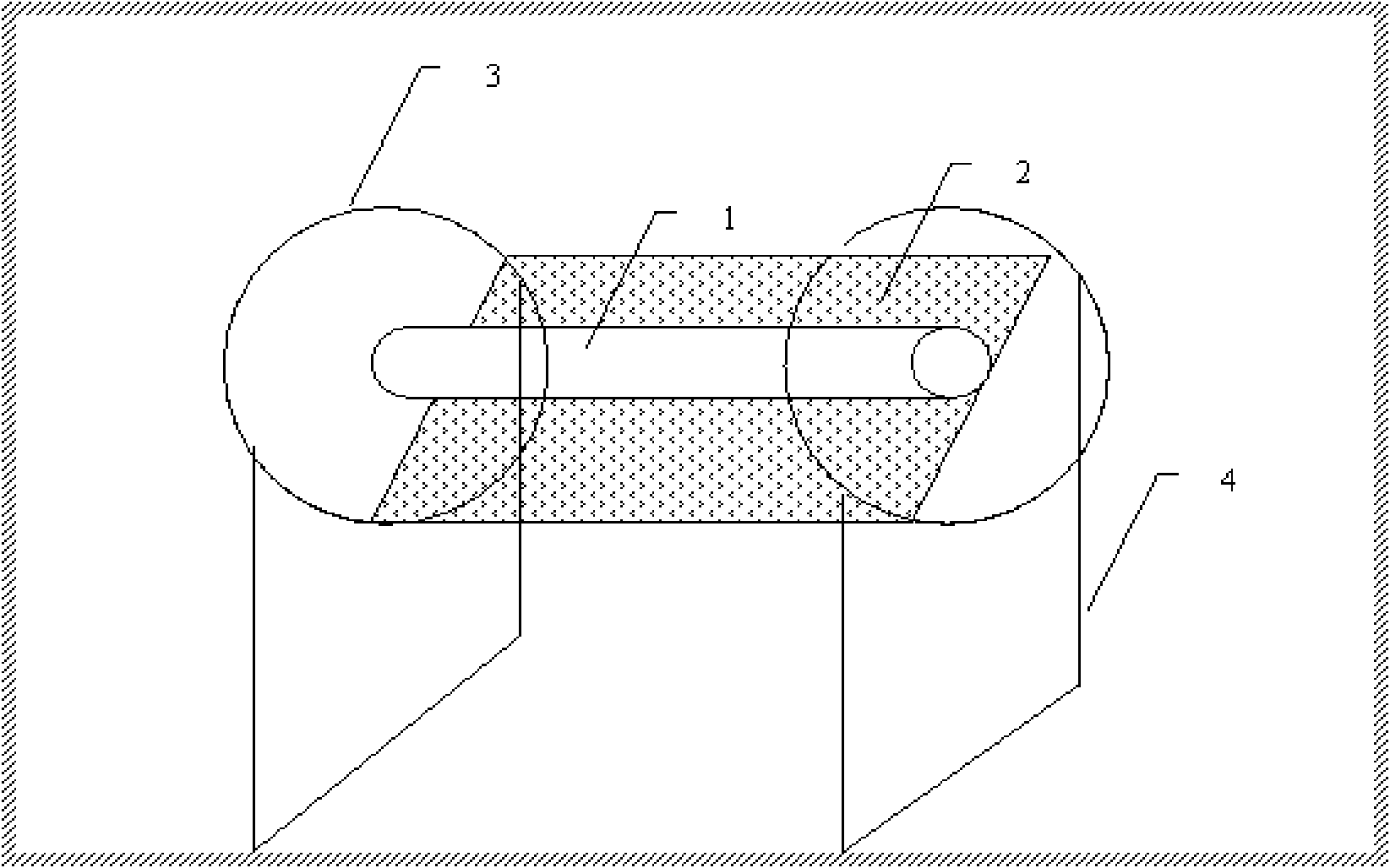
[0069] Embodiment 1: Fresnel mirror solar line focus tracking system

[0070] A linear focusing Fresnel reflector (1) is adopted, and the solar energy utilization device is a heat pipe arranged inside the vacuum, and a solar selective coating is arranged on the heat pipe, and the Fresnel reflector is arranged on the rings at both ends, The Fresnel reflector can move along the orbit of the ring, the vacuum heat collecting tube is fixed on the ring, and the vacuum heat collecting tube remains motionless during the operation of the Fresnel reflector.

Embodiment 2

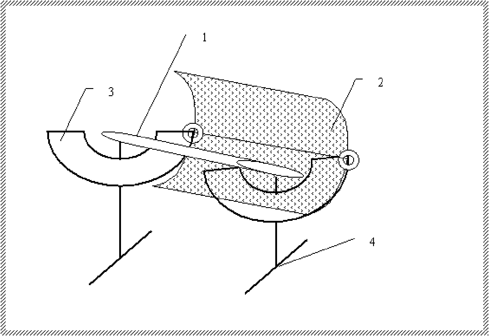
[0071] Embodiment 2: Parabolic mirror arc tracking system

[0072] The solar mirror is a parabolic mirror (2), and the solar energy utilization device (1) is a heat exchange tube. The fluid enters from one end of the heat exchange tube and flows out from the other end. The fluid uses heat transfer oil, and the parabolic mirror is arranged in an arc-shaped On the guide rail, the parabolic mirror can rotate along the arc-shaped parabolic mirror, facing east in the morning, facing the sky at noon, and facing west in the evening, so that the parabolic surface and the sunlight can be kept perpendicular to each other, and the heat exchange tubes are fixed in the arc. On the guide rail, the curved guide rail has a bracket to provide support.

Embodiment 3

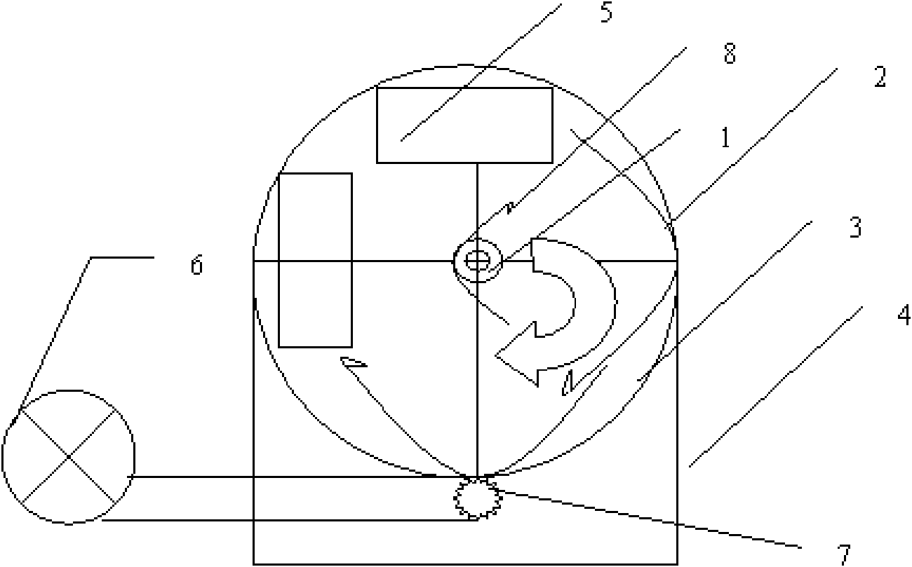
[0073] Embodiment 3: Ring-shaped parabolic tracking system with counterweight

[0074] Such as image 3 As shown, this figure is a side view, the solar mirror (2) is a parabolic reflector; the solar energy utilization device (1) is a solar photovoltaic and photothermal comprehensive utilization system, and the monocrystalline silicon solar panel is arranged inside the vacuum tube At the same time, a water cooling device is provided to provide a heat dissipation device for the solar panel, so that both focused photovoltaic power generation and hot water utilization can be realized. Outside the vacuum tube of monocrystalline silicon, a secondary reflector (8) is also provided. Provide secondary reflected solar light for monocrystalline silicon; the paraboloid and the counterweight (5) form a lever with the focal axis of rotation as the fulcrum, and the paraboloid follows the sun along the direction of the arrow in the figure from morning to noon; the paraboloid is fixed in a cir...


PUM


Abstract

The invention discloses a system and an array for tracking solar energy linearly. In the invention, various solar energy optical mirrors of which the focuses are in a straight line are adopted. In a solar energy tracking process, the solar energy optical mirrors move on an axis of a straight focus line instead of an axis of the bottom line of the conventional solar energy optical mirror, and the focus line is kept still all the time or at rest relative to the ground. In the invention, the structural design that the focus line does not move is adopted, so a heat tube can be applied in heat transfer of the system; and meanwhile, other heavy solar energy-using equipment, such as solar energy photovoltaic generating equipment, a stirling generator and other kinds of large equipment, can be arranged on the focus line, so the solar energy tracing and utilization can be realized by a small drive force. The invention provides an array structure of the system to facilitate massive solar energy utilization, particularly the application of the solar energy in aspects of solar energy thermal power generation, solar energy heating, solar energy cooking, solar energy refrigeration and the like.

Description

technical field [0001] The invention relates to the utilization of solar energy, especially the linear tracking with the focus of the solar tracking being a straight line, the tracking of an array and the utilization thereof. Background technique [0002] Solar tracking mainly consists of three types: trough type, tower type and butterfly type. Because the trough type system is one-way tracking, the relative technical difficulty is relatively low. At the same time, due to the solar energy selective coating and vacuum tube technology, it has industrial production in the temperature range of 100-400 degrees. Therefore, it can be mass-produced quickly, and the earliest commercial application in the world is the trough system. [0003] The main tracking method of the trough system in the world is to set a heat exchange tube at the focal line position of the trough system, fill the heat exchange tube with heat transfer oil, and the motor drives the flow of heat transfer oil to re...

Claims


Application Information

Patent Timeline
Patent Type & Authority Applications(China)
IPC IPC(8): F24J2/38F24S50/20
CPCY02E10/47
Inventor 李建民
Owner BEIJING WISWORD HI TECH
Why Eureka
Try Eureka