
Driving device and driving method of data line of liquid crystal display

A technology of a liquid crystal display and a driving method, applied in the field of a data line driving device of a liquid crystal display, can solve the problems of large driving current and high power consumption of the driving circuit, and achieve the effects of reducing power consumption and driving current

Inactive Publication Date: 2010-09-15
BOE TECH GRP CO LTD +1
View PDF0 Cites 21 Cited by
  • Summary
  • Abstract
  • Description
  • Claims
  • Application Information

AI Technical Summary

Problems solved by technology

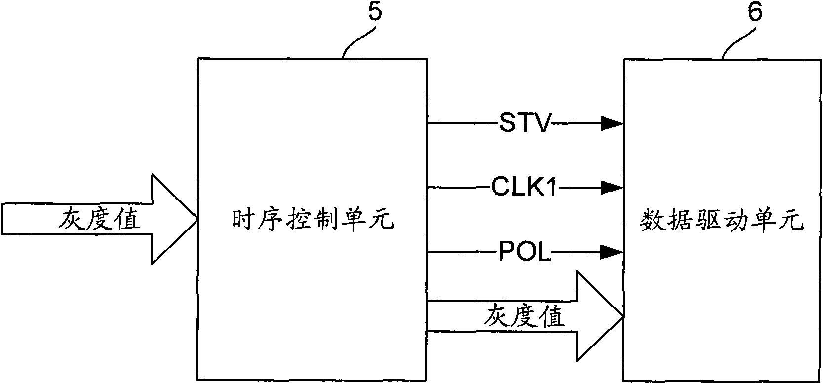
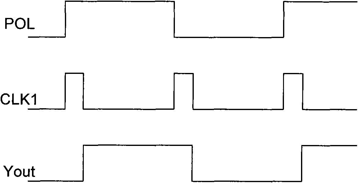
[0003] The problem with this driving method in the prior art is that the power consumption of the driving circuit is proportional to f2×V×I, where f is The driving frequency, that is, the refresh frequency of the liquid crystal display, usually the refresh frequency is 60Hz, 75Hz or 120Hz, V is the driving voltage amplitude, and I is the driving current, that is to say, when the driving frequency and the driving voltage amplitude are the same, the driving The greater the current, the greater the power consumption of the drive circuit
The existing technology adopts the dot inversion driving method, and each frame needs to charge and discharge the sub-pixels, and the driving current is relatively large, so the power consumption of the driving circuit is also large.

Method used


Image

  • Driving device and driving method of data line of liquid crystal display
  • Driving device and driving method of data line of liquid crystal display
  • Driving device and driving method of data line of liquid crystal display

Examples


no. 1 example

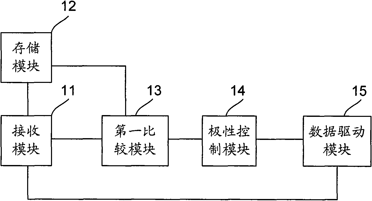
[0049] Such as Figure 5 Shown is the flow chart of the first embodiment of the liquid crystal display data line driving method of the present invention, including:

[0050] Step 101, the receiving module receives the gray value corresponding to each sub-pixel of each frame of image;

[0051] Step 102, the storage module stores the gray value corresponding to each sub-pixel of each frame of image received;

[0052] Step 103, the first comparison module compares the gray value corresponding to each sub-pixel of the current frame image received by the receiving module with the gray value corresponding to each sub-pixel of the adjacent previous frame image stored in the storage module value to compare;

[0053] Step 104, the polarity control module sets the polarity of the voltage applied on both sides of each sub-pixel according to the comparison result of the first comparison module, and compares the gray value of the current frame with the gray value of the adjacent previous...


PUM


Abstract

The invention discloses a driving device and a driving method of a data line of a liquid crystal display. In the drive method, a polarity control module sets the polarity of voltage applied to both sides of sub-pixels, the corresponding polarity of a sub-pixel in which the difference of the gray-scale value of a current frame and the gray-scale value of an adjacent previous frame is smaller than or equal to a first preset value is set to be same with the polarity of the adjacent previous frame, and the corresponding polarity of a sub-pixel in which the difference of the gray-scale value of a current frame and the gray-scale value of an adjacent previous frame is greater than the first preset value is set to be opposite to the polarity of the adjacent previous frame; and a data driving module generates a voltage signal corresponding to the gray-scale value received by a receiving module according to the polarity set by the polarity control module, and the voltage signal is input into a data line. The method provided by the invention does not reverse the corresponding polarity of the sub-pixel in which the difference of the gray-scale value of the current frame and the gray-scale value of the adjacent previous frame is smaller than or equal to the first preset value, so that the drive current can be decreased, and further, the power consumption of a drive circuit is decreased.

Description

technical field [0001] The invention relates to drive control technology, in particular to a liquid crystal display data line drive device and a drive method. Background technique [0002] In the prior art, the liquid crystal display usually adopts a dot inversion driving method, and each pixel of the liquid crystal display usually includes three sub-pixels of red (R), green (G), and blue (B). For the pixel, during the display time of the xth frame, a forward voltage is applied to both sides of the liquid crystal (that is, the voltage applied to the pixel electrode is higher than the voltage applied to the common electrode); During the display time, a negative voltage is applied to both sides of the liquid crystal (that is, the voltage applied to the pixel electrode is lower than the voltage applied to the common electrode). For the subpixel in the mth row and the nth column of the liquid crystal display, a negative voltage is applied to both sides of the liquid crystal dur...

Claims


Application Information

Patent Timeline
IPC IPC(8): G09G3/36G09G5/02
Inventor 张亮
Owner BOE TECH GRP CO LTD
Learn More