Cushion type operating platform for solar modules at later stage of production

A technology of solar modules and consoles, which is applied in the manufacture of electrical components, semiconductor devices, and final products. It can solve problems such as battery sheet rupture and battery components being bent under pressure, so as to ensure quality, facilitate storage, and reduce the probability of damage. Effect

Inactive Publication Date: 2010-09-15
EGING PHOTOVOLTAIC TECHNOLOGY CO LTD
View PDF2 Cites 13 Cited by
  • Summary
  • Abstract
  • Description
  • Claims
  • Application Information

AI Technical Summary

Problems solved by technology

Currently, post-processing consoles such as figure 1 As shown, it includes a worktable 1 and a support frame 2. The support frame 2 is composed of a frame structure surrounded by four equal-length legs 21 and an "I"-shaped reinforcing bar 22. The worktable 1 is horizontally installed on the support frame 2. Above, the area of ​​the worktable 1 is larger than the area of ​​the upper end of the frame structure surrounded by the platform feet 21, and the reinforcing rod 22 is fixedly installed on the middle and lower sections of the four platform feet 21, and the length and width of the worktable 1 are larger than that of the framed battery assembly. Length and width, place the framed solar cell module on the work surface 1, the frame of the solar cell module is in contact with the work surface 1, the middle laminate is in a suspended state, inspection tools, warning labels and grounding diagrams Put them in the tool box. During the subsequent cleaning, inspection, warning stickers and grounding chart operations, if there are tools on the workbench or violations of operating procedures, pressure will be exerted on the surface of the components, causing the battery components to bend under pressure. As a result, the cells in the module are broken

Method used


Image

  • Cushion type operating platform for solar modules at later stage of production
  • Cushion type operating platform for solar modules at later stage of production
  • Cushion type operating platform for solar modules at later stage of production

Examples


Embodiment Construction

[0011] Specific embodiments of the present invention will be described below in conjunction with the accompanying drawings.

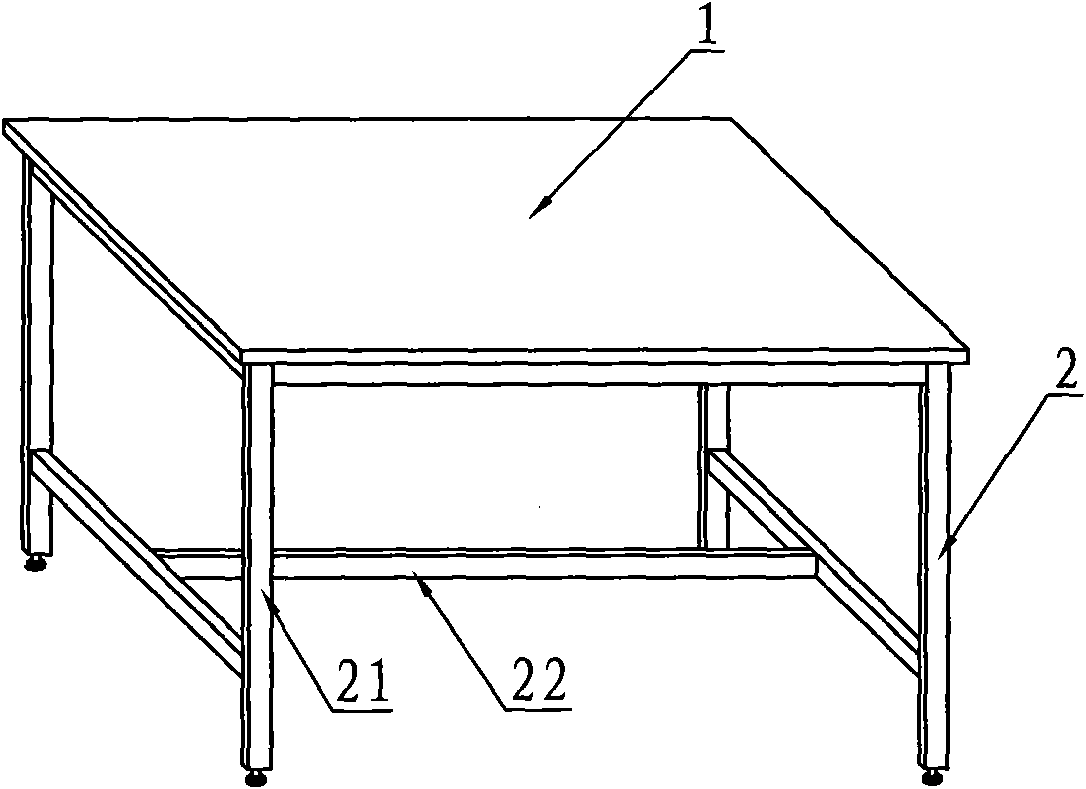
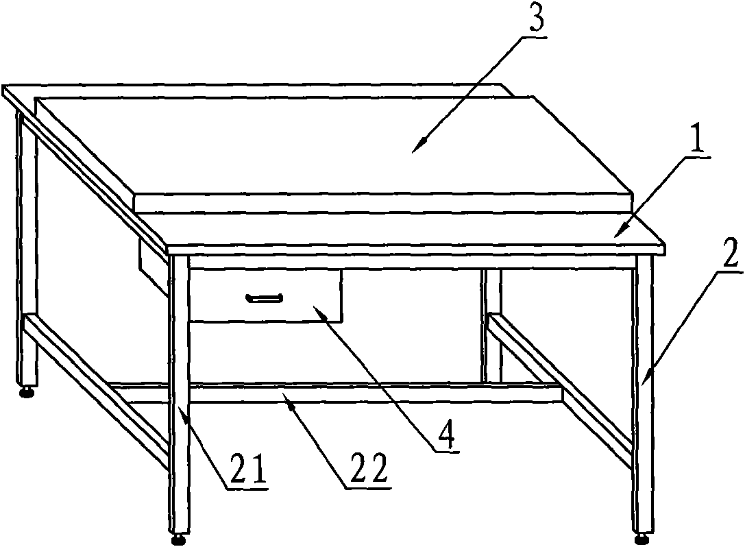
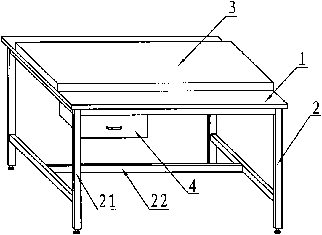
[0012] The post-production operation table of the cushion type solar module, such as figure 2 As shown, it includes a work surface 1, a support frame 2, a highly elastic cushion 3 and a drawer 4. The work surface 1 is horizontally installed on the top of the support frame 2, and the support frame 2 is a frame structure surrounded by four legs 21 of equal length. It is composed of an "I"-shaped reinforcing rod 22, and the "I"-shaped reinforcing rod 22 is fixed on the middle and lower sections of the four table feet 21. Two drawers 4 are arranged below the work surface 1, and the highly elastic cushion 3 is arranged on the Above the work surface 1, and located in the center of the work surface 1, the length and width of the work surface 1 are greater than the length and width of the solar cell module frame after the frame, and the length and width of the...


PUM


Abstract

The invention discloses a cushion type operating platform for solar modules at a later stage of production. The table top of the operating platform is provided with a high-elasticity cushion of which the length and width correspond to those of a laminated sheet in a frame of the framed solar module; and the thickness of the high-elasticity cushion is greater than the maximum thickness of tools used in the subsequent procedure. The high-elasticity cushion supports the laminated sheet in the frame of the solar module, so the laminated sheet cannot be pressed to bend even if the solar module is subjected to accidental pressure in the subsequent cleaning, checking and other operating processes, and the self gravity of the laminated sheet and the pressure applied on the upper surface press the high-elasticity cushion to recess and deform first and cannot cause the breakage of battery plates in the module; a drawer arranged reduces the probability of damaging the battery plates caused by placing the tools on the table top by mistake to the largest extent; and even if the tools are remained on the high-elasticity cushion, the tools can be pressed into the high-elasticity cushion first, and cannot damage the battery plates in the module as long as the thickness of the high-elasticity cushion is greater than that of the tools.

Description

Technical field: [0001] The invention relates to a device for solar component production, in particular to a workbench for post-production operation of solar component. Background technique: [0002] Encapsulation is a key step in the production of solar cell components. Without good packaging equipment, good cell components cannot be produced even with good cell component materials. The encapsulation of the solar cell can not only ensure the life of the battery, but also enhance the resistance strength of the solar cell. The high quality and long life of the product are the key to win the customer's approval. The main production process of solar cell modules is to lay the qualified solar cell silicon wafer strings with glass, EVA, glass fiber, and backsheet according to a certain level. The laying level requirements are: from bottom to top, glass, EVA, battery silicon String, EVA, Fiberglass, Backplane. When laying, the relative position requirements between the layers s...

Claims


Application Information

Patent Timeline
Patent Type & Authority Applications(China)
IPC IPC(8): H01L31/18
CPCY02P70/50
Inventor 刘志刚周锦慧
Owner EGING PHOTOVOLTAIC TECHNOLOGY CO LTD
Why Eureka
Try Eureka