High-resolution and low-spurious-frequency synthesizer of UHF (Ultrahigh Frequency) frequency band

A frequency synthesizer, high-resolution technology, applied in the direction of automatic power control, electrical components, etc., can solve the problems of the output frequency cannot be covered, the system noise is difficult to control, the frequency resolution is reduced, etc., to reduce debugging complexity, improve Frequency resolution, effect of reducing settling time

Inactive Publication Date: 2010-09-15
BEIJING BBEF SCI & TECH
View PDF0 Cites 12 Cited by
  • Summary
  • Abstract
  • Description
  • Claims
  • Application Information

AI Technical Summary

Problems solved by technology

The disadvantage of the analog quadrature mixer is that it needs to suppress the sideband and carrier leakage, and the sideband and carrier leakage are different for different carrier frequencies, and all need to be adjusted
If an ordinary single mixer is used in this scheme, its function is to combine the two input frequencies f 1 , f 2 The multiplication operation is performed, and the resulting frequency is f 1 , f 2 , f 1 -f 2 , f 1 + f 2 etc.; if the mixed signal f 1 2 , the frequency signal f generated at this time 2 -f 1 and f 1 + f 2 Very close, due to the limitations of the process and bandwidth of the analog bandpass filter, it is difficult to obtain the desired output frequency range, or the output frequency cannot cover the desired frequency band
On the other hand, since the DDS operating clock is inversely proportional to its frequency resolution, if the DDS operating clock is increased, its frequency resolution will decrease
At this time, more circuit links need to be introduced, making the system noise difficult to control

Method used


Image

  • High-resolution and low-spurious-frequency synthesizer of UHF (Ultrahigh Frequency) frequency band
  • High-resolution and low-spurious-frequency synthesizer of UHF (Ultrahigh Frequency) frequency band
  • High-resolution and low-spurious-frequency synthesizer of UHF (Ultrahigh Frequency) frequency band

Examples


Embodiment Construction

[0026] For further elaborating the technical means and effects that the present invention takes for reaching the intended invention purpose, below in conjunction with accompanying drawing and preferred embodiment, to its specific implementation mode, structure, feature and effect of (title) proposed according to the present invention, Details are as follows.

[0027] The aforementioned and other technical contents, features and effects of the present invention will be clearly presented in the following detailed description of preferred embodiments with reference to the drawings. Through the description of the specific implementation mode, when the technical means and functions adopted by the present invention to achieve the predetermined purpose can be obtained a deeper and more specific understanding, but the accompanying drawings are only for reference and description, and are not used to explain the present invention be restricted.

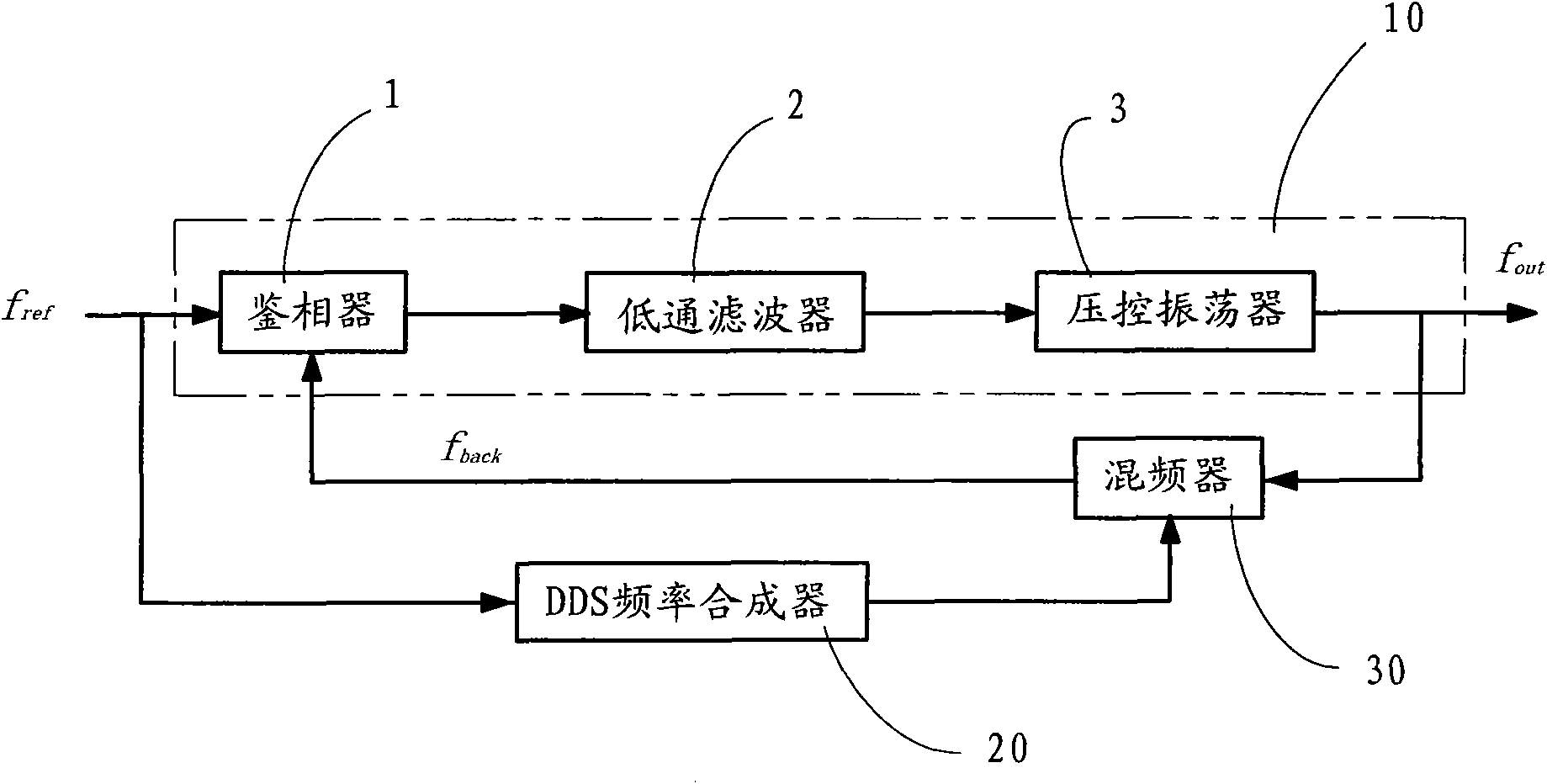
[0028] Such as figure 1 As shown, a fr...


PUM


Abstract

The invention relates to a frequency synthesizer, in particular to a high-resolution and low-spurious-frequency synthesizer of a UHF (Ultrahigh Frequency) frequency band, comprising a phase detector, a phase-locked loop, a DDS frequency synthesizer and a quadrature mixer, wherein the phase-locked loop comprises a low-pass filter and a voltage controlled oscillator; the DDS frequency synthesizer is a double-frequency output DDS frequency synthesizer; the phase detector is used for receiving reference signals and dividing the signals, the low-pass filter is connected with the phase detector to supply voltage control signals, a voltage control oscillator is connected with the low-pass filter to supply output signals, the quadrature mixer is coupled among the voltage control oscillator, the DDS frequency synthesizer and the phase detector, and the DDS frequency synthesizer is connected between a reference signal and the quadrature mixer. The frequency synthesizer greatly increases the frequency resolution (0.0024Hz), inhibits stray, reduces the stabilization time and can especially obtain the same high-resolution frequency signals in arbitrary frequency bands.

Description

technical field [0001] The invention relates to a frequency synthesizer, in particular to a high-resolution and low spurious frequency synthesizer used in the UHF frequency band of terrestrial television broadcasting. Background technique [0002] Frequency synthesizers in electronic systems are used to generate any range of frequencies from a single fixed time reference or oscillator. Many existing radio devices, mobile phones, mobile receivers, high-energy accelerators, radio and television transmission systems, etc., are equipped with frequency synthesizers. The national standard of the UHF frequency band has higher requirements for the frequency synthesizer of terrestrial TV broadcasting than the frequency synthesizer of the ordinary communication system: according to the national standard, the frequency resolution in the UHF frequency band (470MHz-860MHz) is below 1Hz; its characteristics are high bandwidth, high resolution, low phase noise. Therefore, the frequency s...

Claims


Application Information

Patent Timeline
IPC IPC(8): H03L7/197
Inventor 梁富林龙平
Owner BEIJING BBEF SCI & TECH
Why Eureka
Try Eureka