Methods for automatically detecting topology of optical transmission monitoring networks and implementation device

A network monitoring and automatic detection technology, applied in transmission systems, digital transmission systems, data exchange networks, etc., can solve problems such as difficult troubleshooting of optical path failures, rising maintenance costs, complex topology of optical transmission monitoring networks, etc., to achieve fast processing speed, The effect of consuming less resources and less bandwidth

Inactive Publication Date: 2010-09-15
SHENZHEN INFINOVA
View PDF5 Cites 11 Cited by
  • Summary
  • Abstract
  • Description
  • Claims
  • Application Information

AI Technical Summary

Problems solved by technology

[0003] As the topology of the optical transmission monitoring network is more complex, if intelligent management is not adopted, it will bring various negative effects. For example, because there are more optical paths in the optical network system, there will be more fault points, making it more difficult to troubleshoot optical path faults. At the same time, more maintenance manpower and material resources are required; the complexity of the optical network will also lead to an increase in the professional skills of maintenance personnel. The monitoring system needs to be equipped with more professional maintenance personnel, which will also lead to an increase in maintenance costs, etc.

Method used


Image

  • Methods for automatically detecting topology of optical transmission monitoring networks and implementation device
  • Methods for automatically detecting topology of optical transmission monitoring networks and implementation device
  • Methods for automatically detecting topology of optical transmission monitoring networks and implementation device

Examples


Embodiment Construction

[0034] The present invention will be described in further detail below in conjunction with the embodiments and with reference to the accompanying drawings.

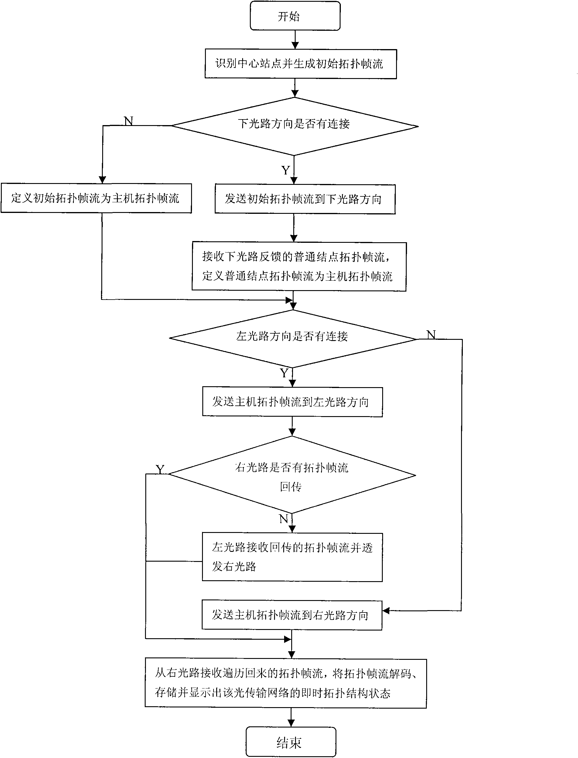
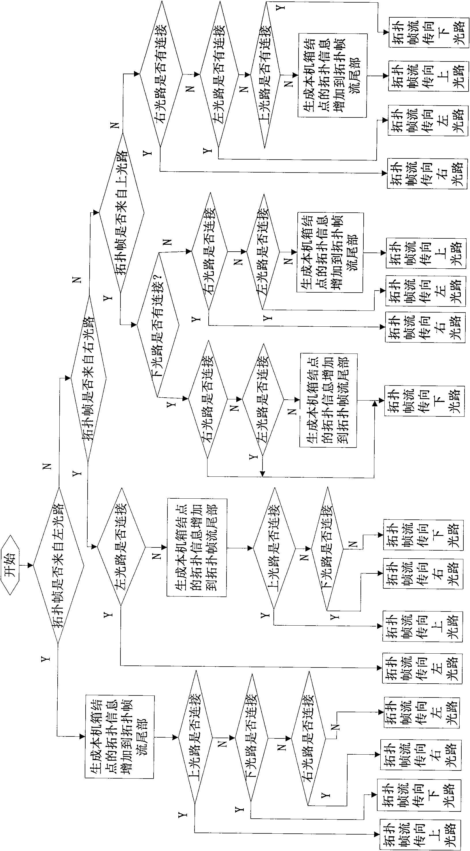
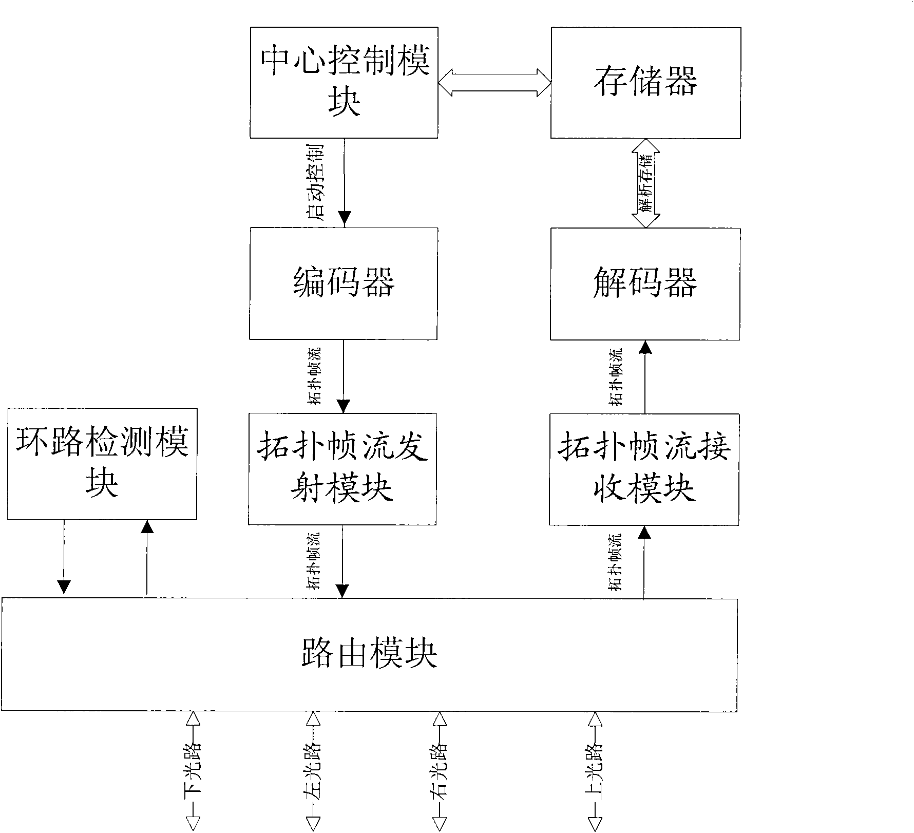
[0035] A device for automatically detecting optical transmission monitoring network topology, including a control module, a routing module with four optical path interfaces, a memory, an optical path interface detection module, a topology frame stream receiving module, a topology frame stream transmitting module, an encoder and a decoder . It is defined that: the optical path interface in the higher-level topology network is the left optical path and the right optical path, the optical path interface in the lower-level topology network is the lower optical path and the upper optical path, the main data flow entrance is the right optical path and the lower light path, and the main data flow exit For the left optical path and the upper optical path.

[0036] 1. When the device is a central site machine on a loop topology, ...


PUM


Abstract

The invention discloses methods for automatically detecting the topology of optical transmission monitoring networks and an implementation device. The methods comprise a central site topological method and an ordinary node topological method, wherein a central node is used for initiating a topological query from a central node and downwards routing from a central main site according to a policy of sub-path priority and breaking path return; if the node has multiple sub topological structures, different priority levels of the sub topological structures can be defined, and the priority levels are sequentially traversed from high levels to low levels. The topological routing algorithm can guarantee that all nodes in an optical network can be traversed under the condition of any open path or closed loop and the traversing sequence is consistent with a pseudo coding sequence. The invention also discloses the device for implementing the method for automatically detecting the topology of the optical transmission monitoring networks. The invention is realized based on a synchronous clock transmission system and a hardware structure, has various characteristics of high topology speed (ns level), high reliability, support of chain type, ring type, ring cutting, star-shaped and mixed type optical networks, low implementation cost, and the like and is suitable for the intelligent topology processing of large and medium scaled and even very-large-scaled monitoring optical transmission networks in the field of security.

Description

technical field [0001] The invention relates to a method for detecting network topology, in particular to a method for automatically detecting the topology of an optical transmission monitoring network in the field of security monitoring and an implementation device. Background technique [0002] With the continuous expansion of the current security field and the gradual upgrading of the security market, traditional security optical transceivers (point-to-point, node, convergence, etc.) can no longer meet the increasing system requirements, and a new generation of security business optical transmission monitoring network has emerged as the times require. The new generation of security business optical transmission monitoring network has the following advantages: larger system capacity, more complex topology, stronger self-healing protection functions, higher service quality, more humanized and intelligent, etc. [0003] As the topology of the optical transmission monitoring ...

Claims


Application Information

Patent Timeline
Patent Type & Authority Applications(China)
IPC IPC(8): H04L12/26H04B10/08H04B10/077H04B10/079
Inventor 秦永涛
Owner SHENZHEN INFINOVA
Why Eureka
Try Eureka