Large-size direct type LED backlight source and preparation method

An LED backlight source, direct type technology, applied in the field of high-power LED backlight source structure and its preparation, to achieve the effects of reduced manufacturing and use costs, prolonged heat dissipation problems, and low energy consumption

Inactive Publication Date: 2010-09-22
SOUTH CHINA UNIV OF TECH
View PDF3 Cites 23 Cited by
  • Summary
  • Abstract
  • Description
  • Claims
  • Application Information

AI Technical Summary

Problems solved by technology

Therefore, the problem of heat dissipation of the circuit and its chip is particularly prominent.

Method used


Image

  • Large-size direct type LED backlight source and preparation method
  • Large-size direct type LED backlight source and preparation method
  • Large-size direct type LED backlight source and preparation method

Examples


Embodiment 1

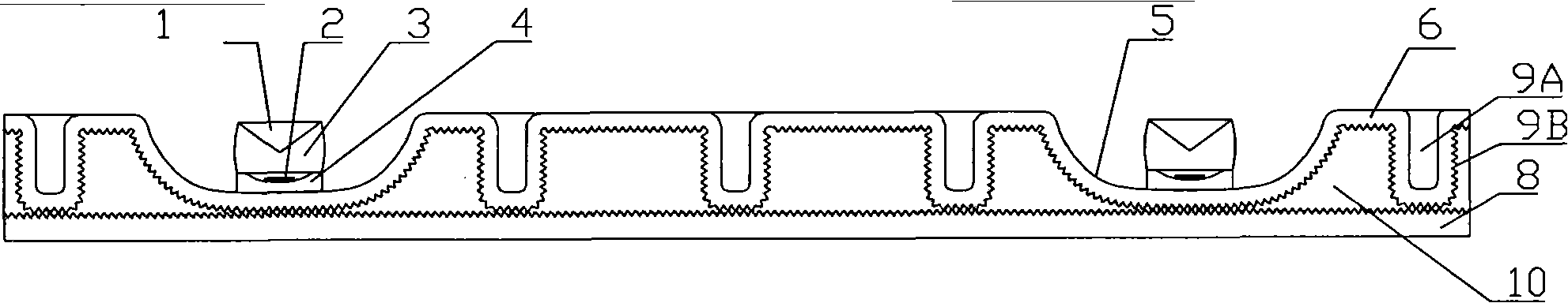
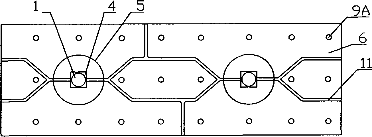
[0037] Such as figure 1 As shown, a large-size direct-lit LED backlight includes a metal substrate 6, a soaking plate, and an edge-emitting LED. A plurality of reflective bowls 5 are stamped on the metal substrate 6. The reflective bowls 5 are evenly distributed on the metal substrate 6 and have a bowl-shaped free-form surface structure; the reflective bowls 5 are provided with support columns 9A formed by stamping of the metal substrate 6. The support columns 9A is a columnar structure recessed inward.

[0038] Such as figure 2 As shown, a layer of Al is plated on the surface of the metal substrate 6 by the method of micro-arc oxidation 2 O 3 Micro-arc oxide film, used as high thermal conductivity insulating dielectric layer, Al 2 O 3 The surface of the micro-arc oxide film is covered with a wiring circuit 11 connected to the LED chip 2.

[0039] The lower wall shell is a frame-shaped structure, which is stamped and formed by an aluminum rectangular plate, and is set at the lower...

Embodiment 2

[0051] Such as Figure 7 As shown, a large-size direct-lit LED backlight includes a metal substrate 6, a soaking plate, and an edge-emitting LED. A plurality of reflective bowls 5 are stamped on the metal substrate 6, and the reflective bowls 5 are evenly distributed on the metal substrate 6, which has a bowl-shaped free-form surface structure.

[0052] The metal substrate 6 is a copper substrate, the surface of which is covered with an insulating dielectric layer, and the surface of the insulating dielectric layer is covered with a wiring circuit 11 connected to the LED chip 2. The insulating medium layer generally adopts high thermal conductivity epoxy glass brazing cloth or epoxy resin, and its thickness is 0.08mm-0.1mm.

[0053] The lower surface of the metal substrate 6 is provided with micro-protrusions 9B with a pitch of 0.1-0.2mm and a height of 0.1-0.2mm; the lower wall shell 8 is a frame-shaped structure, stamped and formed from a copper rectangular plate, and is set on ...


PUM

PropertyMeasurementUnit
thicknessaaaaaaaaaa
thicknessaaaaaaaaaa
lengthaaaaaaaaaa

Abstract

The invention discloses a large-size direct type LED backlight source and a preparation method. The backlight source structure comprises an edge emission type LED, a metal basal plate and a lower wall casing; the edge emission type LED comprises a conical half-reflecting semi-permeable mirror, an LED chip, packaging resin and an LED lamp holder; a plurality of light reflecting bowls are punched on the metal basal plate and are evenly distributed on the metal basal plate, the lower wall casing is in a frame-shaped structure and is arranged at the lower end of the metal basal plate, a hollow cavity is formed between the lower wall casing and the metal basal plate, the lower surface of the metal basal plate and the upper surface of the lower wall casing are provided with fine structures in the hollow cavity, fine structures at the lower ends of the light reflecting bowls are connected with the fine structure at the upper surface of the lower wall casing, and a liquid absorption core is formed; and support columns are arranged between the adjacent light reflecting bowls, have equal heights with the light reflecting bowls and are connected with the fine structure at the upper surface of the lower wall casing, and a liquid absorption core is formed. The invention provides an LED backlight source structure compromising the performance and the energy consumption under the precondition of low cost and realizing the lightness and the thinness of a large-size LED and a manufacturing process.

Description

Technical field [0001] The invention relates to a light-emitting diode (LED) backlight structure of a liquid crystal display (LCD), in particular to a high-power LED backlight structure used on a large-size LCD and a preparation method thereof. The invention is suitable for all applications where the LED point light source needs to be converted into a surface light source. Background technique [0002] Since the LCD itself does not emit light, it is necessary to find a backlight source as the light source of the thin-film liquid crystal display. Therefore, the performance of the backlight source determines the external visual sense of the LCD. The backlight source is to convert the point light source or the line light source in the backlight module into a uniformly distributed surface light source, and use a film to control the viewing angle, improve the optical characteristics, and make the LCD achieve the purpose of perfect display. The LCD backlight is a module that combines ...

Claims


Application Information

Patent Timeline
Patent Type & Authority Applications(China)
IPC IPC(8): F21S8/00F21V7/00F21V17/00F21V19/00F21V29/00G02F1/13357H01L33/60F21Y101/02F21V29/506F21V29/56F21V29/89
Inventor 李勇夏润生何成彬曾志新
Owner SOUTH CHINA UNIV OF TECH
Why Eureka
Try Eureka