Solar multi-directional tracking heat pipe utilization system

A solar heat pipe and solar energy technology, applied in the field of solar energy utilization, can solve the problems of inability to guarantee thermal insulation requirements, high cost, and high heat loss, and achieve the effects of reducing heat loss in collection and transmission, reducing energy consumption, and low cost

Inactive Publication Date: 2010-09-22
BEIJING WISWORD HI TECH
View PDF0 Cites 1 Cited by
  • Summary
  • Abstract
  • Description
  • Claims
  • Application Information

AI Technical Summary

Problems solved by technology

In the process of tracking solar energy, the heat transfer oil moves together in the pipe, and the bellows are used at the heat transfer oil pipe and the outflow end to realize the connection between the moving pipe and the non-moving pipe; because the bellows need high temperature resistance and high reliability, etc. Requirements, so it becomes a key component, and at the same time, this kind of connection cannot guarantee the insulation requirements, so the heat loss and cost of the system are high

Method used


Image

  • Solar multi-directional tracking heat pipe utilization system
  • Solar multi-directional tracking heat pipe utilization system
  • Solar multi-directional tracking heat pipe utilization system

Examples


Embodiment 1

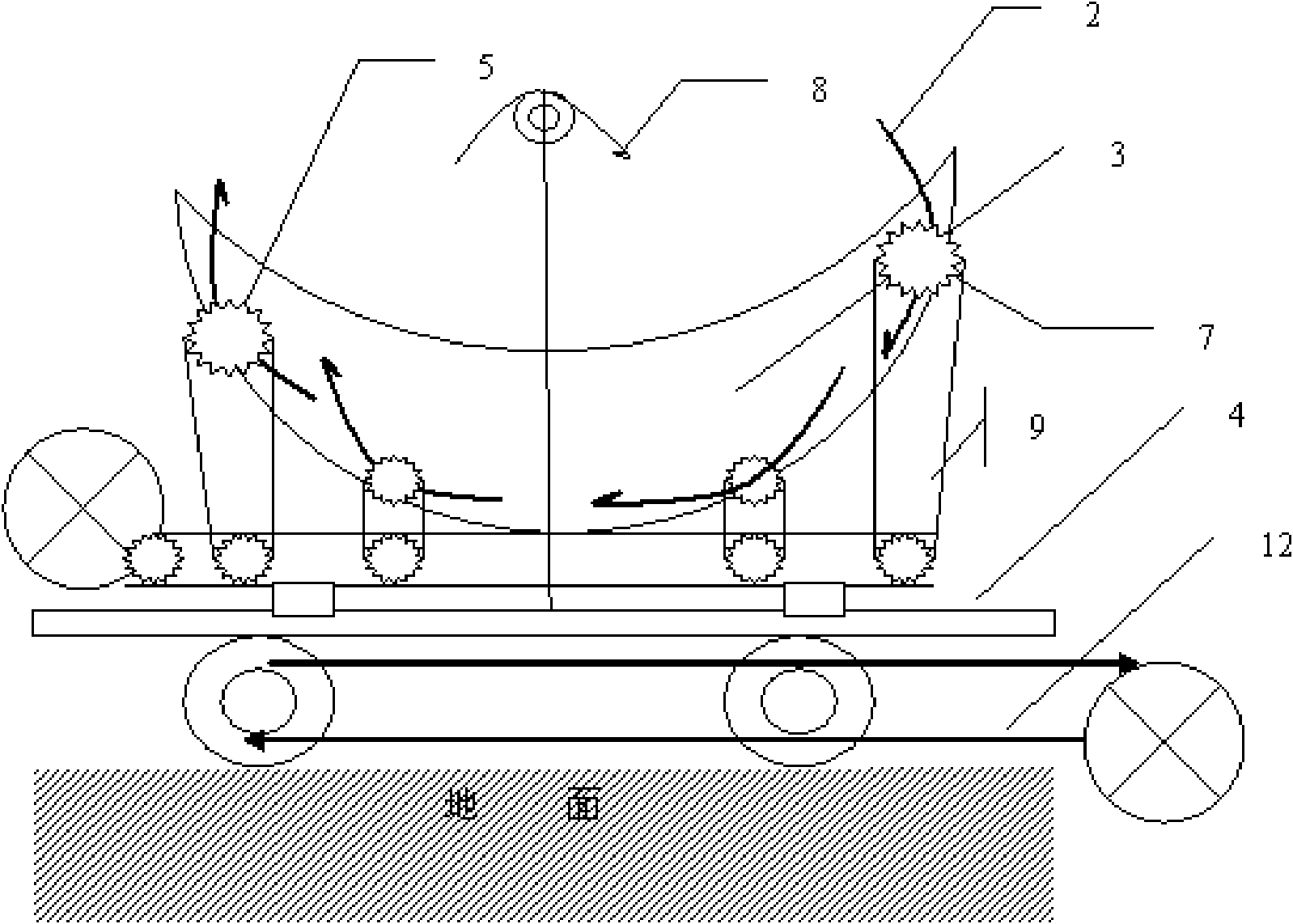
[0055] Embodiment 1: Multi-parabolic reflective heat pipe utilization system

[0056] This figure is a side view, the solar mirror (2) is four parabolic reflectors (2), the heat pipe utilization system (1) is a heat pipe arranged inside the glass tube, the outside of the heat pipe is provided with a solar coating, and the parabolic mirror is arranged on On a parabolic device, a shaft is arranged on each parabolic mirror, and the solar mirror can rotate along the rotating shaft (5). The drive of the mirror bracket (4) realizes the driving of the rotating shaft (5) and the driving of the solar mirror bracket in the parabolic device to realize the overall tracking of the solar energy; the four solar mirrors realize the tracking of the solar energy through different movements At the same time, the solar light is focused to the evaporation end (10) of the heat pipe, and various utilizations of heat energy are realized through the heat exchanger (11) arranged at the condensation end...

Embodiment 2

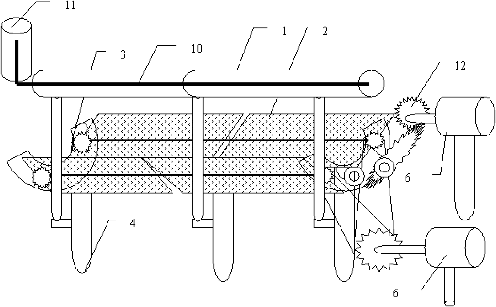
[0057] Embodiment 2: Multi-glass mirror heat pipe utilization system

[0058] Such as figure 2 As shown, this example uses two sets of glass mirrors to realize solar tracking, wherein each set of solar mirrors is two glass mirrors, and the tracking systems of the two sets of glass mirrors are connected in series; the evaporation end of the heat pipe is set on the vacuum tube, and the condensation end is set on-line focusing In the external area of ​​the system, a heat exchanger is installed at the condensing end to realize various applications such as power generation, heating, and cooling of thermal energy. Four glass reflectors are fixed on three ring-shaped devices, the power drive device is a motor (6), the power transmission device is a gear mechanism arranged on the ring, and the motor drives the gear arranged on the ring through the gear mechanism , so that the glass mirror is turned on the ring, at the same time, the driving device (12) to the solar mirror support (4...

Embodiment 3

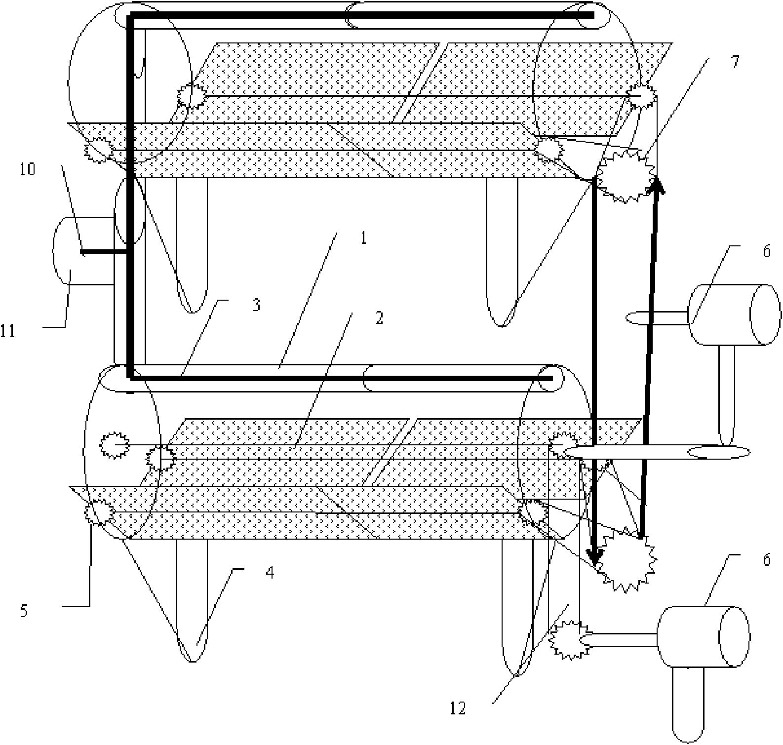
[0059] Embodiment 3: Multi-Fresnel Mirror Array Tracking Heat Pipe Utilization System

[0060] Such as image 3 As shown, this case is a multi-mirror array tracking system, using four Fresnel mirrors, the power drive device is a motor, the motor drives two gears set on the focal line shaft through the power transmission equipment of the chain, and also sets There is a system that drives the solar mirror bracket (3) to provide the driving force, so that the solar mirror system can move along the semi-circular bracket, so that multi-directional tracking can be realized; the solar tracking of the 2*2 array can be realized, and the heat pipe system The evaporation end is set in the focal line area of ​​the online focusing system, and the condensation end is set outside the focal line area, so as to realize the utilization of various thermal energy of solar energy.


PUM


Abstract

The invention discloses a solar multi-directional tracking heat pipe utilization system. In the system, a group of solar optical mirrors consisting of a plurality of reflecting mirrors, a Fresnel mirror, and a plane mirror are adopted; a revolving shaft of each mirror is arranged on a solar mirror support of different shapes; each solar optical mirror can rotate around the shaft, and meanwhile the solar mirror support can move, so that the multi-directional tracking that the solar mirror rotates around a starting shaft and moves together with the solar mirror support is realized; as the multi-directional tracking reduces the difficulty in homotaxial tracking, the range of the focused cylinder area is reduced, and the focusing multiple and the using temperature are increased; as solar heat pipe utilization equipment is arranged in a cylinder interval on ground or a building, when the solar mirror moves, the solar heat pipe utilization equipment can keep still, the focal length is variable zooming and tracking, and the solar heat pipe utilization equipment realizes the utilization of the focused and tracked solar energy in a cylinder; and the application of the solar energy, such as thermal power generation, heating, refrigeration, hot water, boiling water and the like, is realized by using the heat pipe as a solar energy converter and perfectly combining the heat pipe technology and the optical mirror technology. The invention provides an array structure of the system, which is suitable for systems of different scales, and simultaneously suitable for large-scale utilization of the solar energy, particularly the heat utilization of the solar energy.

Description

technical field [0001] The invention relates to the utilization of solar energy, especially the linear tracking with the focus of solar energy focusing on a straight line and the tracking of an array to realize comprehensive applications such as thermal power generation, heating, cooling, hot water, and boiling water of solar energy. Background technique [0002] The thermal application of solar energy mainly adopts glass vacuum tube heat pipe technology to realize the application of hot water at a temperature of 60 degrees. The high temperature thermal utilization of solar energy mainly adopts three solar energy collection technologies of trough type, tower type and butterfly type to realize high temperature solar thermal power generation application . The existing hot water application with a low temperature of 60 degrees is a small-scale household application. Since there is no tracking system, the temperature cannot be raised and the use of high temperature cannot be rea...

Claims


Application Information

Patent Timeline
Patent Type & Authority Applications(China)
IPC IPC(8): F24J2/32F24J2/38F24J2/52F24J2/40F24J2/08F24J2/10F24S10/95F24S23/30F24S23/70F24S50/20
CPCY02E10/44Y02E10/47
Inventor 李建民
Owner BEIJING WISWORD HI TECH
Why Eureka
Try Eureka