High-speed motor with rotor cooling structure
A rotor cooling, high-speed motor technology, applied in cooling/ventilation device, magnetic circuit shape/style/structure, electrical components, etc., can solve the problems of reduced rotation accuracy of bearing spindle system, thermal deformation of the spindle, increased motor vibration amplitude, etc. Achieve stable fit clearance and working performance, reduce thermal deformation, and reduce vibration amplitude.
- Summary
- Abstract
- Description
- Claims
- Application Information
AI Technical Summary
Problems solved by technology
Method used
Image

Examples
Embodiment Construction
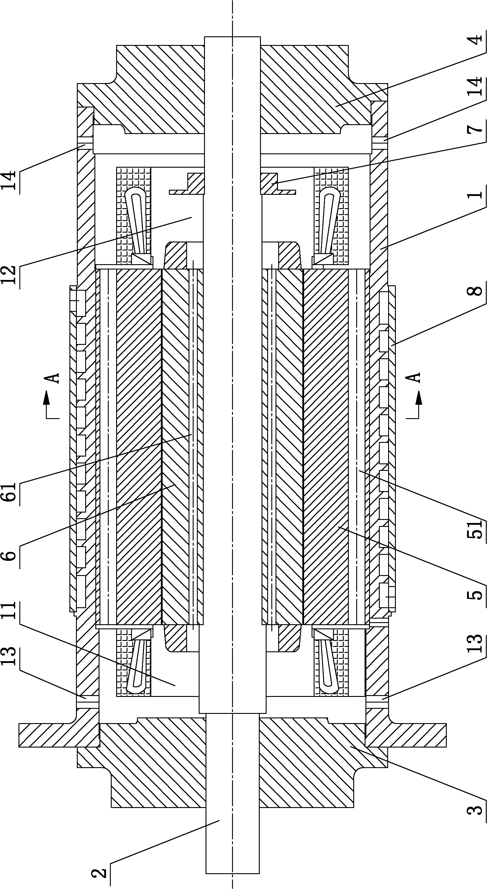
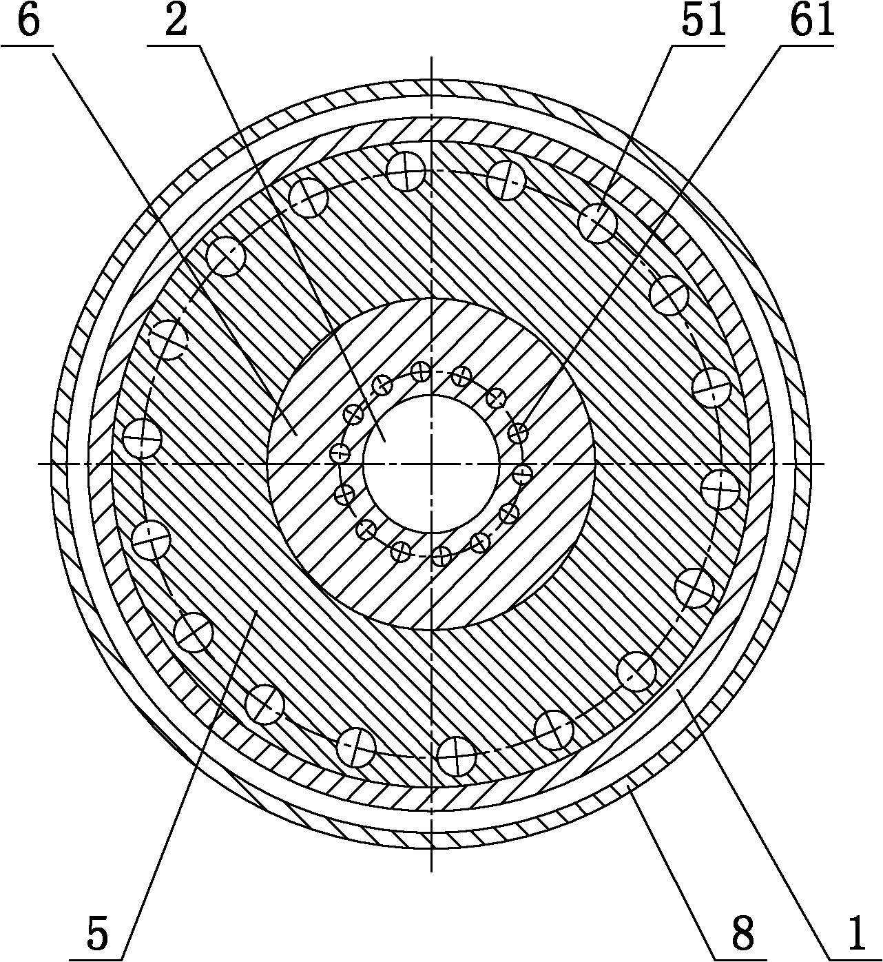
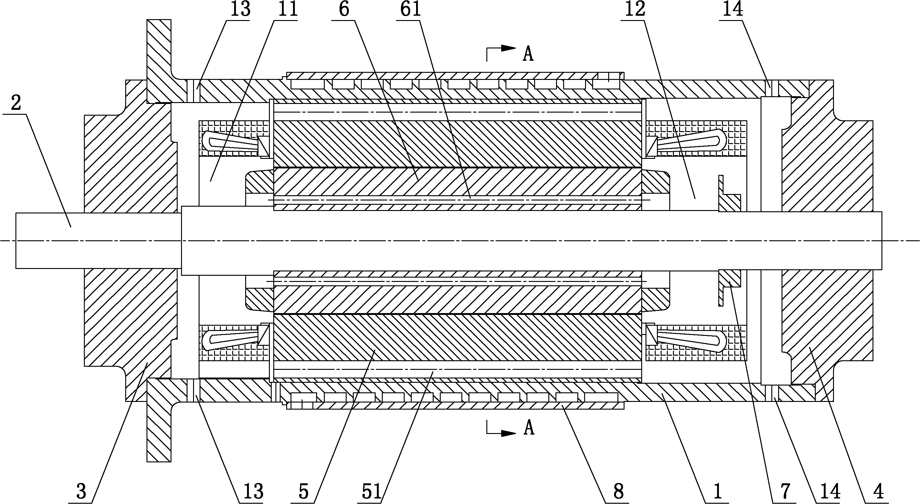
[0019] figure 1 with figure 2 It shows an embodiment of a high-speed motor with a rotor cooling structure of the present invention, including a motor housing 1, a motor main shaft 2, a front flange assembly 3, a rear flange assembly 4, a motor stator 5 and a motor rotor 6, described The motor stator 5 is sleeved in the motor housing 1, the motor rotor 6 is sleeved in the motor stator 5, the front flange assembly 3 is installed at the front end of the motor housing 1 and forms a front cavity 11, and the rear flange assembly 4 Installed at the rear end of the motor housing 1 to form a rear cavity 12, the motor shaft 2 is set inside the motor rotor 6 and the front and rear ends are respectively supported on the front flange assembly 3 and the rear flange assembly 4, the motor rotor 6 There is a ventilation hole 61 connecting the front cavity 11 and the rear cavity 12 on the top, the motor stator 5 is provided with a return air hole 51 connecting the front cavity 11 and the rear...
PUM
 Abstract
Description
Claims
Application Information
 - R&D
- Intellectual Property
- Life Sciences
- Materials
- Tech Scout
- Unparalleled Data Quality
- Higher Quality Content
- 60% Fewer Hallucinations
Browse by: Latest US Patents, China's latest patents, Technical Efficacy Thesaurus, Application Domain, Technology Topic, Popular Technical Reports.
© 2025 PatSnap. All rights reserved.Legal|Privacy policy|Modern Slavery Act Transparency Statement|Sitemap|About US| Contact US: help@patsnap.com