Micromechanical system

A micromechanical system and micromechanical technology, applied in the field of micromechanical systems, can solve problems such as increased cost and increased consumption of micromechanical systems

Inactive Publication Date: 2010-09-22
ROBERT BOSCH GMBH
View PDF1 Cites 8 Cited by
  • Summary
  • Abstract
  • Description
  • Claims
  • Application Information

AI Technical Summary

Problems solved by technology

Generally speaking, these measures increase the expenditure in the production, installation and / or operation of the micromechanical system
This can also disadvantageously lead to increased costs

Method used


Image

  • Micromechanical system
  • Micromechanical system
  • Micromechanical system

Examples


Embodiment Construction

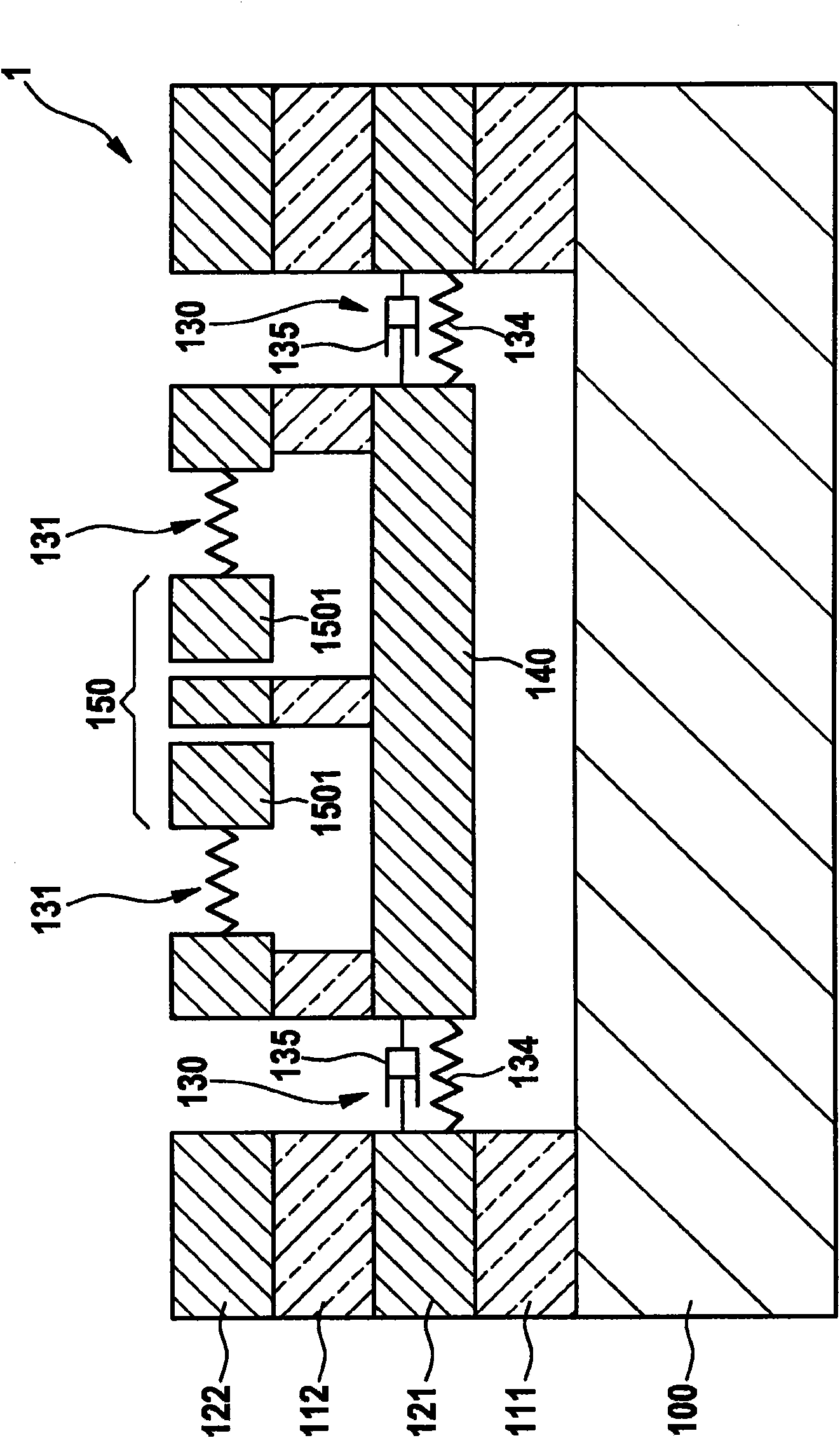
[0014] Figure 1A The micromechanical system according to the first embodiment of the invention is shown in a schematic side view along a cross section. The first micromechanical system 1 is here produced in a layered stack on the substrate 100 . The layered stack comprises a first consumable layer 111 , a first functional layer 121 , a second consumable layer 112 and a second functional layer 122 . The substrate 100 may include a semiconductor substrate, such as a silicon substrate, wherein the first and second consumable layers 111, 112 may include semiconductor oxides, such as silicon dioxide, and wherein the first and second functional layers 121, 122 may include Semiconductors, such as silicon. Furthermore, the semiconductor of the first and second functional layers 121, 122 may include silicon, polysilicon, amorphous silicon and / or epitaxially grown polysilicon (EPI). Such micromechanical systems, such as the first micromechanical system 1 , can be produced by sacrific...


PUM


Abstract

The invention relates to a micromechanical system (1) which comprises a substrate (100), a suspension (130), a base (140) and a micromechanical sensor (150), the suspension (130) movably carrying the base (140) above the substrate (100) and the micromechanical sensor (150) being located on the base (140).

Description

technical field [0001] The invention relates to a micromechanical system. Background technique [0002] Micromechanical systems, such as micromechanical transducers, inertial sensors, acceleration sensors, low-g acceleration sensors, rotational speed sensors, and related components are now widely used. These systems are thus used, for example, to activate airbags in vehicles (KFZ) or also to detect vibrations in computer hard disks. In this case, the micromechanical sensor usually includes a micromechanically configured movable mass, the movement of which is detected as a result of acceleration, vibration or movement. Furthermore, in particular the capacitance between the mass and the reference electrode can be measured continuously, since this capacitance depends on the distance of the mass from the reference electrode. [0003] Furthermore, micromechanical systems are demanding, in part, demanding environments of use due to their wide range of applications. The environm...

Claims


Application Information

Patent Timeline
Patent Type & Authority Applications(China)
IPC IPC(8): B81B7/00
CPCG01P15/0802G01P15/08B81B7/0012
Inventor T·皮尔克A·弗兰克K·克尔
Owner ROBERT BOSCH GMBH
Why Eureka
Try Eureka