Cylinder with devices for distributing lubricants

A lubricant and cylinder technology, applied in cylinders, cylinder heads, engine components, etc., can solve problems such as high cost and environmental pollution, and achieve the effects of increasing working life, reducing consumption, and low lubricant consumption

Active Publication Date: 2010-09-29
WAERTSILAE SCHWEIZ AG
View PDF8 Cites 7 Cited by
  • Summary
  • Abstract
  • Description
  • Claims
  • Application Information

AI Technical Summary

Problems solved by technology

Apart from considerable costs especially for large engines,

Method used


Image

  • Cylinder with devices for distributing lubricants
  • Cylinder with devices for distributing lubricants
  • Cylinder with devices for distributing lubricants

Examples


Embodiment Construction

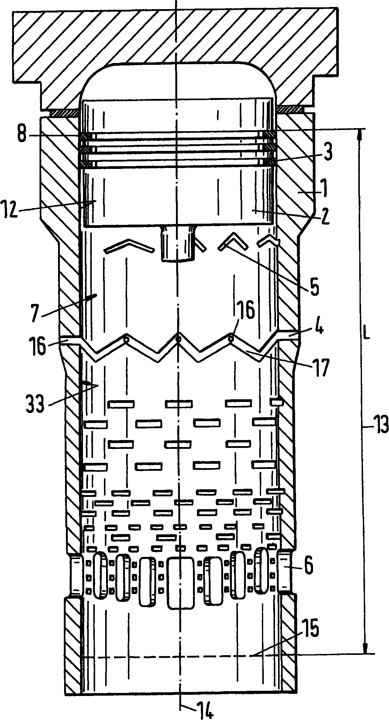
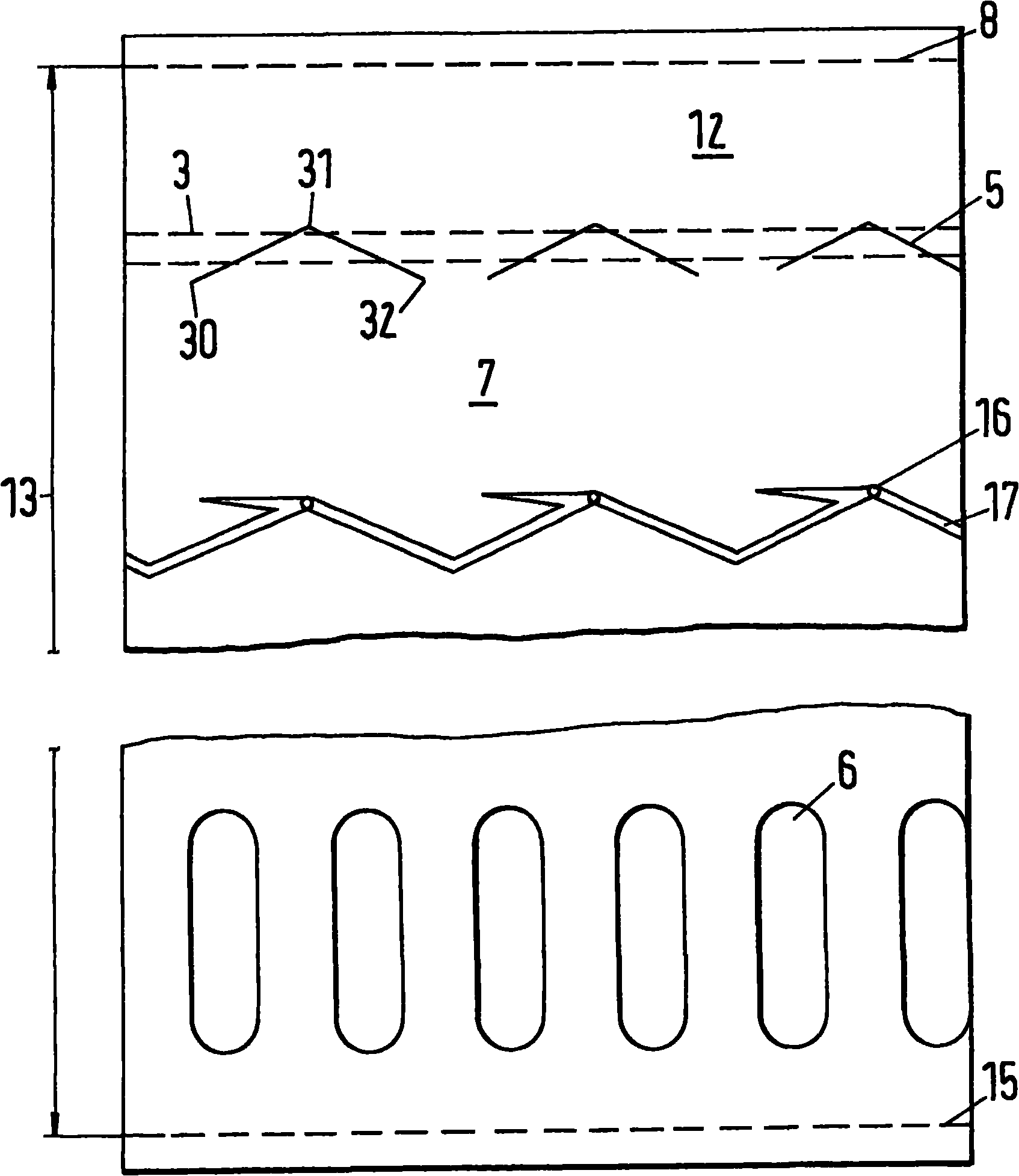
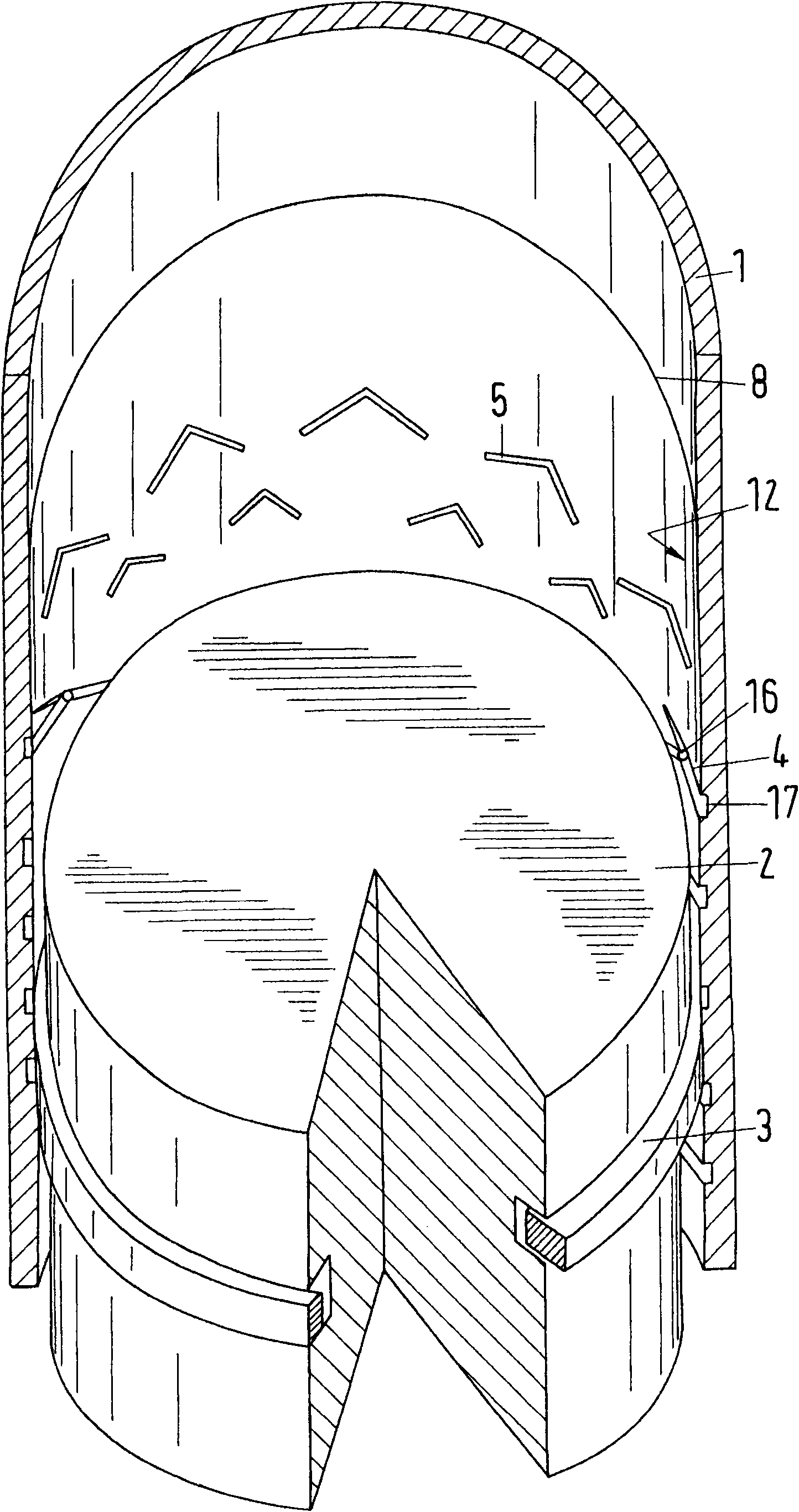
[0056] figure 1 A section through a cylinder 1 arranged in a piston engine is shown. The piston engine is a two-stroke or four-stroke engine, especially a large engine, which is in most cases a large diesel engine. Such large diesel engines are currently equipped with cylinders with internal diameters typically greater than 190 mm. Typical diameters are between 250 and 1000mm. A piston reciprocates inside the cylinder and is connected to a rotatable drive shaft via a crankshaft. This reciprocating movement of the piston occurs between top dead center and bottom dead center. figure 1 The piston is shown in the top dead center position. If a section perpendicular to the cylinder axis 14 is placed through the top dead center of the uppermost piston ring, this plane will intersect the inner wall of the cylinder along a line encircling what shall from now on be called the top dead center zone 8 . In the case of a vertical arrangement of the cylinders, the upper dead center zo...


PUM

PropertyMeasurementUnit
Diameteraaaaaaaaaa

Abstract

The invention relates to a cylinder with devices for distributing lubricants, in particular, to a cylinder for a reciprocating piston engine holding a piston prepared with at least a piston ring. The cylinder has a slit for holding and distributing lubricants. The slit is arranged at a sliding surface. The slit includes a first part and a second part, wherein the first part includes a first end and a second end. The first end has a first orifice and the second end has a second orifice. The second part includes a second end and a third end. The third end includes a third orifice. First and third orifices are arranged under the piston ring via the slit and the second orifice is arranged above the pistion ring via the slit, thereby the pistion ring could form a channel for lubricants between an inner space of the cylinder above the piston ring and the inner space of the cylinder under the piston ring when it is located between one of first and third orifices and the second orifice.

Description

technical field [0001] The invention relates to a cylinder for a reciprocating piston engine comprising means for lubricant distribution. Background technique [0002] In large two-stroke engines or likewise four-stroke engines, the distribution of the lubricant proves to be critical due to the large surface to be wetted. Lubricant movement enters the inner space of the cylinder through a limited number of supply ports arranged at the periphery of the cylinder. In order to distribute the liquid lubricant evenly on the inner wall of the cylinder, peripheral grooves are provided, as shown for example in document FR1174532. However, it has been found during long-term operation of the engine that these grooves are especially in the very heavily loaded part of the cylinder (which extends approximately 15% in the direction of the bottom dead center of the piston from the top dead center of the uppermost piston ring) suffer from significant material loss. Due to the high pressur...

Claims


Application Information

Patent Timeline
IPC IPC(8): F02F1/20
CPCF02F1/20
Inventor K·拉斯K·加卢斯卡
Owner WAERTSILAE SCHWEIZ AG
Why Eureka
Try Eureka