Current sensing circuit

A current sensing and circuit technology, applied in the field of converters, can solve the problems of distortion of sensing current value, decrease of sensing efficiency, inability to sense tiny current value, etc.

Inactive Publication Date: 2010-09-29
DONGBU HITEK CO LTD
View PDF5 Cites 7 Cited by
  • Summary
  • Abstract
  • Description
  • Claims
  • Application Information

AI Technical Summary

Problems solved by technology

Thus, the sensing efficiency drops sharply
[0012] Third, due to the use of OP-AMP 34 to configure negative feedback, it increases the limitation on bandwidth
[0013] Fourth, a bias is generated by the gain of the OP-AMP 34, and if the temperature changes, the difference in the temperature coefficients of the common gate TR 36, the power TR 12, and the sensing TR 32 will distort the waveform of the signal
[0014] Fifth, according to the range of the input voltage of the OP-AMP 34, the distortion of the sensing current value is generated
[0015] Sixth, due to the limitation of the output voltage range of the OP-AMP 34, it is impossible to sense tiny current values ​​(eg, 100mA~3A)
[0018] However, as the capacity of the DC-DC converter increases, the above-mentioned problems arise or become more serious

Method used


Image

  • Current sensing circuit
  • Current sensing circuit
  • Current sensing circuit

Examples


Embodiment Construction

[0033] Reference will now be made in detail to specific embodiments of the invention, examples of which are illustrated in the accompanying drawings. Wherever possible, the same reference numbers will be used throughout the drawings to refer to the same or like parts.

[0034] A current sensing circuit according to a preferred embodiment of the present invention will be described in detail below with reference to the accompanying drawings.

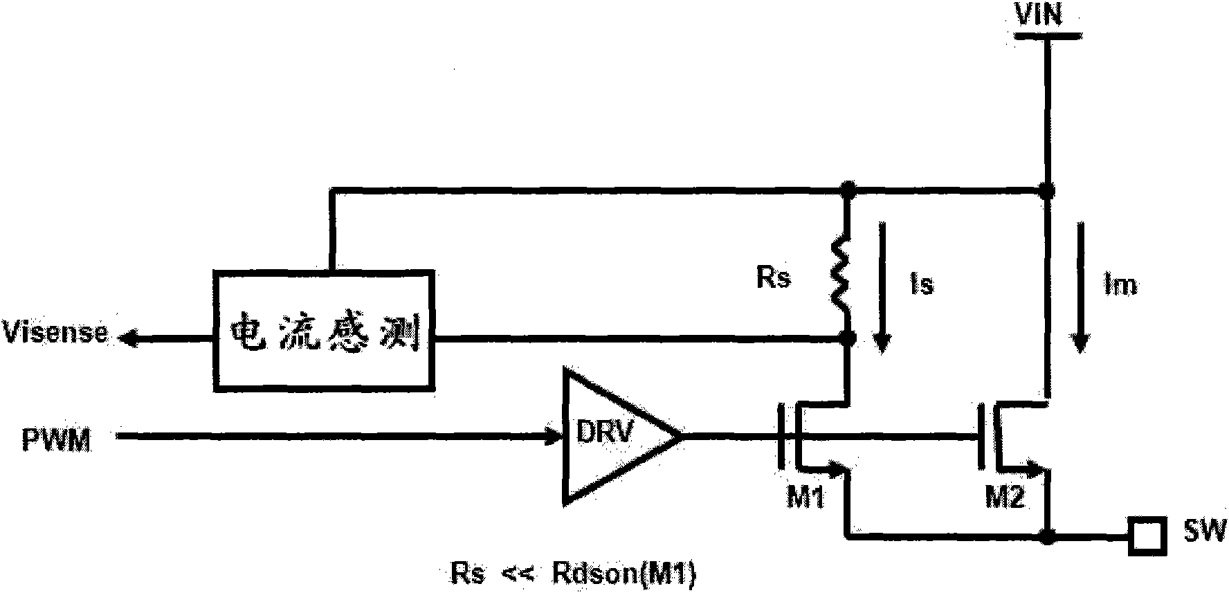
[0035] figure 2 is the circuit diagram used to describe the current sensing structure.

[0036] refer to figure 2 , M2 represents the main power switch, and M1 represents the sensing TR. The sensing TR may include a field effect transistor (FET).

[0037] The main current Im (eg, sense current) flowing through the main power switch M2 is copied to the sensing TR at a ratio of N:1.

[0038] The replicated current Is generates a sensing voltage Vsen by flowing through the resistor Rs.

[0039] The current sensing unit detects the dif...


PUM


Abstract

A current sensing circuit includes a power transistor, a sensing transistor M1 configured to copy a current flowing through the power transistor at a predetermined ratio, a current sensing resistor R1 configured to detect a voltage from the current copied by the sensing transistor M1, an input resistor configured to convert an input voltage VIN to a current, a cross self-biasing cascade block configured to adjust currents at both ends of the input resistor, and a common gate transistor M3 and a reference resistor R4 configured to convert a current output of the input resistor to a final sense voltage. Therefore, the invention maximizes the conversion efficiency and minimizes the lost caused by current sensing.

Description

[0001] Related Application Cross Reference [0002] This application claims priority from Korean Patent Application No. 10-2008-0138064 filed on December 31, 2008, the entire contents of which are hereby incorporated by reference. technical field [0003] The present invention relates to a converter, and more particularly, to a current sensing circuit. While the present invention is suitable for a wide range of applications, it is particularly useful for maximizing conversion efficiency and minimizing losses in current sensing. Background technique [0004] Generally, current technology trends of DC-DC converters include miniaturization, high efficiency and large capacity. For miniaturization, traditional board-level system circuits are integrated at the IC (Integrated Circuit) level. In addition, various techniques (eg, current sensing techniques) have been proposed to achieve high efficiency. [0005] Conversely, in order to achieve a large capacitance, the size of the ...

Claims


Application Information

Patent Timeline
Patent Type & Authority Applications(China)
IPC IPC(8): G01R19/00
CPCG01R19/0092H02M2001/0009H02M3/156H02M1/0009H02M1/44H02M3/155
Inventor 河昌佑张桢雅
Owner DONGBU HITEK CO LTD
Why Eureka
Try Eureka