Method for drying a compressed gas

A technology for compressing gas and drying, which is applied in dryers to dry compressed gas and the drying field of compressed gas. It can solve problems such as high dew point pressure, prolonged heating steps, and unoptimized use of heating power, so as to improve reliability and shorten regeneration time. The effect of minimizing and reducing the number of dryers

Inactive Publication Date: 2010-09-29
ATLAS COPCO AIRPOWER NV
View PDF0 Cites 4 Cited by
  • Summary
  • Abstract
  • Description
  • Claims
  • Application Information

AI Technical Summary

Problems solved by technology

[0004] A disadvantage of the known drying methods for compressed gas is that, depending on the operating state of the dryer and compressor installation, the dew point pressure of the dried compressed gas at the outlet of the dryer can be rela

Method used


Image

  • Method for drying a compressed gas
  • Method for drying a compressed gas
  • Method for drying a compressed gas

Examples


Embodiment Construction

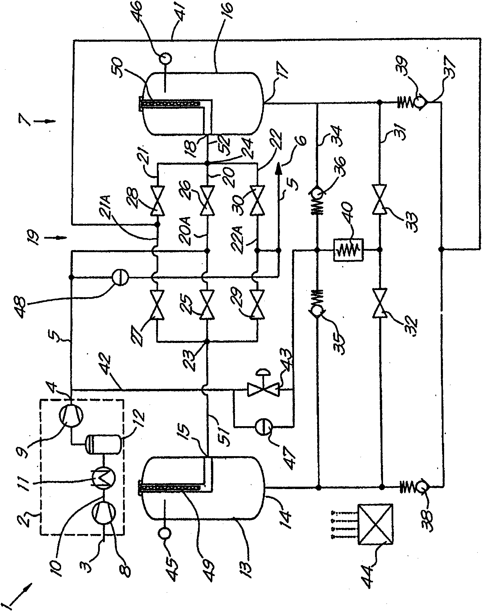
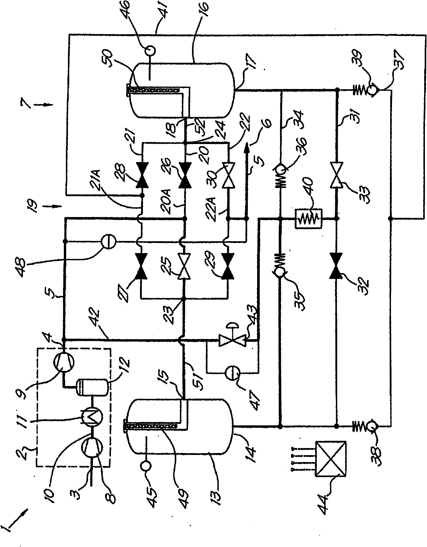
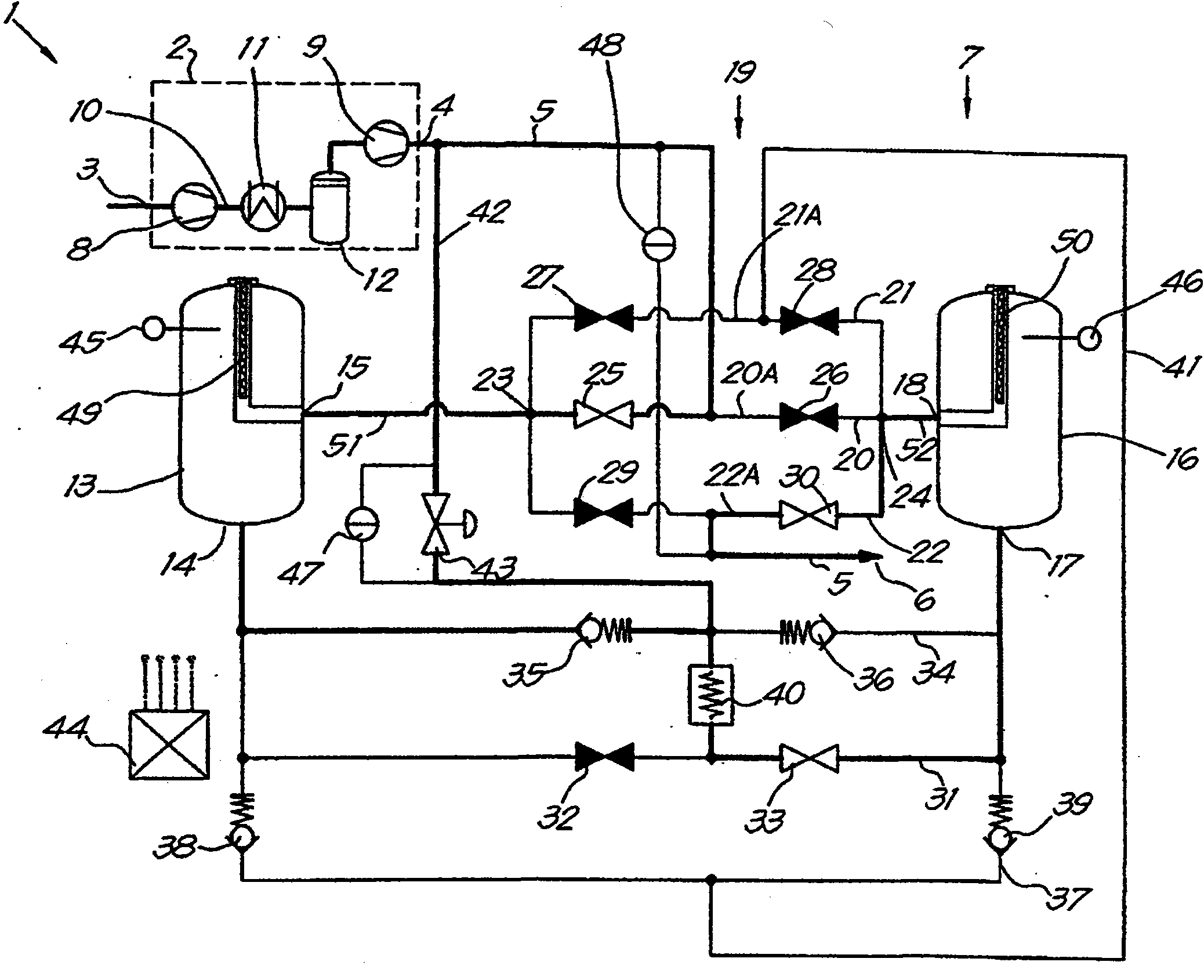
[0035] figure 1 Shown is a compressor device 1, which essentially comprises: a compressor 2 with an inlet 3 and an outlet 4; a compressed air line 5, which connects the outlet 4 of the compressor 2 to a user network 6; and a dryer 7, which combines In the above-mentioned compressed air pipeline 5.

[0036] In this example, the compressor 2 comprises a low-pressure section 8 and a high-pressure section 9 connected in series via a pressure line 10 in which an intercooler 11 and a water separator 12 are incorporated in succession.

[0037] The dryer 7 comprises: a first pressure vessel 13 with an inlet 14 and an outlet 15 containing silica gel or any other desiccant; a second pressure vessel 16 with an inlet 17 and an outlet 18 also containing a desiccant.

[0038] In addition, the drying machine 17 is provided with a distribution device 19, and the distribution device 19 includes three pipelines, which are respectively a first pipeline 20, a second pipeline 21 and a third pipel...


PUM


Abstract

Method for drying compressed gas by means of a dryer (7) with pressure vessels (13 and 16), whereby this method comprises the steps of guiding a first part of the gas to a cooler (40) via a regulating valve (43), and of subsequently drying this first part of the gas in the drying pressure vessel (16); and of heating a second part of the gas so as to regenerate the regenerating pressure vessel (13), whereby, when the temperature in the regenerating pressure vessel (13) rises above an upper limit value, the regulating valve (43) will be shut and, when this temperature drops under a lower limit value, the regulating valve (43) will be opened.

Description

technical field [0001] The present invention relates to a method of drying compressed gas, in particular compressed gas from a compressor installation. [0002] In particular, the present invention relates to a method of drying compressed gas with a dryer having at least two pressure vessels filled with a desiccant or desiccant, the pressure vessels working alternately so that one pressure vessel is busy drying When the gas is compressed, another pressure vessel will be regenerated. Background technique [0003] This drying method is known, whereby to dry the compressed gas coming from the compressor plant, a part of the gas is cooled in a cooling machine before being conveyed through the drying pressure vessel and thus in order to regenerate another pressure vessel, The uncooled portion of the gas is directed through the regeneration pressure vessel to absorb the moisture absorbed by the drying means by means of the heat of compression retained in this portion of the gas t...

Claims


Application Information

Patent Timeline
IPC IPC(8): B01D53/26
CPCB01D2259/402B01D53/0462B01D53/0454B01D2259/4009B01D2259/40003B01D2259/40009B01D53/261
Inventor F·G·M·休伯兰德W·马斯E·尼乌文赫伊兹T·塞森斯
Owner ATLAS COPCO AIRPOWER NV
Why Eureka
Try Eureka