
Special intelligent motive power device of oil pumping unit

A special intelligence and power device technology, applied in the direction of transmission, machine/engine, mechanical equipment, etc., can solve the problems of narrow speed regulation range, high operating cost, large motor capacity, etc., to achieve precise speed regulation and save huge investment Effect

Inactive Publication Date: 2010-10-06
JIANGSU SHENGYUAN GAS POWER +1
View PDF5 Cites 8 Cited by
  • Summary
  • Abstract
  • Description
  • Claims
  • Application Information

AI Technical Summary

Problems solved by technology

[0002] The existing coalbed methane or natural gas pumping units are mainly powered by various speed-regulating motors. Since the operating locations of the pumping units are widely scattered in remote areas, the power required for the motor work must be transmitted through the newly designed and laid power grid. There are shortcomings of large one-time investment in transmission and distribution lines and long payback period; at the same time, due to on-load start-up, the actually configured motor capacity of the speed-regulating motor is too large, the speed-regulating range is narrow, and the power consumption of the pumping unit is too high. Disadvantages such as high consumption, high operating costs, and difficulty in remote monitoring
[0003] In recent years, coalbed methane or natural gas pumping units have also used gas engines as power. However, the function and means of speed regulation of pumping units are simple, and only rely on the speed of the engine to adjust on site. The speed regulation range is narrow and cannot Realize the function of remote speed regulation

Method used


Image

  • Special intelligent motive power device of oil pumping unit
  • Special intelligent motive power device of oil pumping unit
  • Special intelligent motive power device of oil pumping unit

Examples


Embodiment Construction

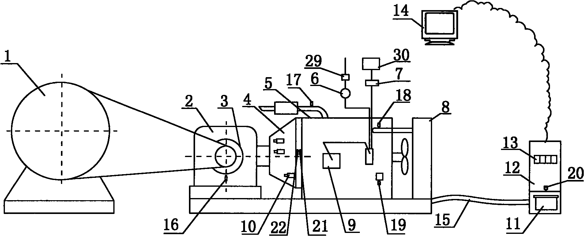
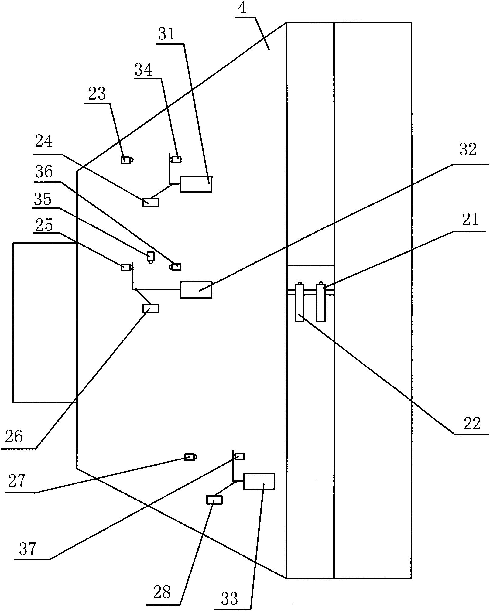
[0025] Such as Figure 1 to Figure 5 As shown, a special intelligent power device for a pumping unit of the present invention, the pumping unit 1 is driven by a variable-diameter output pulley 3, and the variable-diameter output pulley is connected with a fixed-ratio reducer 2, and the fixed-ratio The reducer 2 is connected to the multi-speed transmission 4, the power output end of the oil-air dual-purpose engine 5 is connected to the multi-speed transmission 4, the oil-air dual-purpose engine 5 is connected to the control cabinet 12 through the cable 15, and the control cabinet 12 is connected to the computer 14 through GPRS . The front end of the oil-air dual-purpose engine 5 is connected with the cooling fan water tank 8, the gasoline tank 30 is connected with the oil-air dual-purpose engine 5 through the gasoline pump 7, the solenoid valve 29 is connected with the oil-air dual-purpose engine 5 through the pressure reducing valve 6, and the oil-air dual-purpose engine 5 A ...


PUM


Abstract

The invention relates to a special intelligent motive power device of an oil pumping unit. The oil pumping unit is driven by an output belt pulley with the variable diameter, the output belt pulley with the variable diameter is connected with a speed reducer with the fixed transmission ratio, the speed reducer with the fixed transmission ratio is connected with a multi-gear shifting speed changer, the motive power output end of an oil and gas dual purpose engine is connected with the multi-gear shifting speed changer, the oil and gas dual purpose engine is connected with a control cabinet through a cable, and the control cabinet is connected with a computer through GPRS. The invention can be widely used for the motive power of the oil pumping unit used for the coal bed or natural gas pumping extraction operation, the huge investment of the high-voltage and low-voltage electric network is saved, the electric consumption of the operation of the oil pumping unit is avoided, and the effects of energy saving and exhaust reduction are reached. The invention has wide speed regulation ratio range, can realize remote stepless speed regulation and remote starting and stopping, can reduce the manual perambulation cost, and is favorable for the centralized monitoring of the mass operation of the oil pumping unit.

Description

technical field [0001] The invention relates to a novel intelligent power device specially used for pumping units capable of stepless speed regulation, wide speed regulation ratio, energy saving and intelligence. Background technique [0002] The existing coalbed methane or natural gas pumping units are mainly powered by various speed-regulating motors. Since the operating locations of the pumping units are widely scattered in remote areas, the power required for the motor work must be transmitted through the newly designed and laid power grid. There are shortcomings of large one-time investment in transmission and distribution lines and long payback period; at the same time, due to on-load start-up, the actually configured motor capacity of the speed-regulating motor is too large, the speed-regulating range is narrow, and the power consumption of the pumping unit is too high. It has disadvantages such as large consumption, high operating cost, and difficulty in remote monit...

Claims


Application Information

Patent Timeline
Patent Type & Authority Applications(China)
IPC IPC(8): E21B43/00F02B63/06F02B61/06F16H9/04
Inventor 汤洪辉陆凯亮王国强熊德华郭辉张占军
Owner JIANGSU SHENGYUAN GAS POWER
Learn More