Production process of inner magnetic rotor of magnetic drive pump

A technology of internal magnetic rotor and production process, which is applied to parts, pumps, and pump components of pumping devices for elastic fluids. It can solve problems such as uneconomical, complicated processes, and difficult welding, and achieve low production costs. The effect of simple production process

Inactive Publication Date: 2010-10-06
鸿浩泵业有限公司
View PDF4 Cites 3 Cited by
  • Summary
  • Abstract
  • Description
  • Claims
  • Application Information

AI Technical Summary

Problems solved by technology

[0002] In many industries, it is required to transport high-temperature and strong corrosive media. General metal corrosion-resistant chemical centrifugal pumps cannot meet the requirements. Special alloy pumps are expensive and uneconomical, so fluoroplastic-lined chemical centrifugal pumps or fluoroplastic-lined magnetic pumps are usually used. For pumps, the former uses an external mechanical seal that always leaks and pollutes the environment, while the latter has no leakage. However, since the internal magnetic rotor is made of plastics such as partial difluoride or polyether ketone, although the pressing process is simple, the encapsulation The inner magnetic rotor is safe and reliable, but it cannot withstand high temperature and strong corrosive media. It is also encapsulated with polyperfluoroethylene propylene (F46), but it is a secondary encapsulation process. The process is complicated, the effect is not good, and there are cracks , or the welding process, because the welding performance of polyfluoroethylene propylene (F46) is very poor, it is difficult to weld, and there is leakage. They are all unreliable processes, so they cannot provide a safe and economical resistance. Internal magnetic rotor with high temperature and strong corrosion resistance

Method used


Image

  • Production process of inner magnetic rotor of magnetic drive pump
  • Production process of inner magnetic rotor of magnetic drive pump
  • Production process of inner magnetic rotor of magnetic drive pump

Examples


Embodiment Construction

[0021] The production process of the inner magnetic rotor of a magnetic pump is completed by the following production steps:

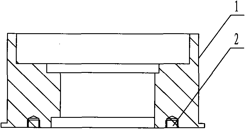
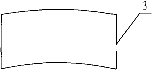
[0022] (a) The inner magnetic rotor base 1 is made of carbon steel, and the phenolic-acetal adhesive is evenly coated on the outer surface of the cleaned inner magnetic rotor base 1 with a thickness of 0.2-0.3 mm. The magnetic material 3 is made of high temperature resistant The magnetic material samarium cobalt (the properties of the magnetic material are shown in the table below), and then the magnetic material 3 is pasted on the inner magnetic rotor base 1, and cured at 180°C for 2 hours;

[0023]

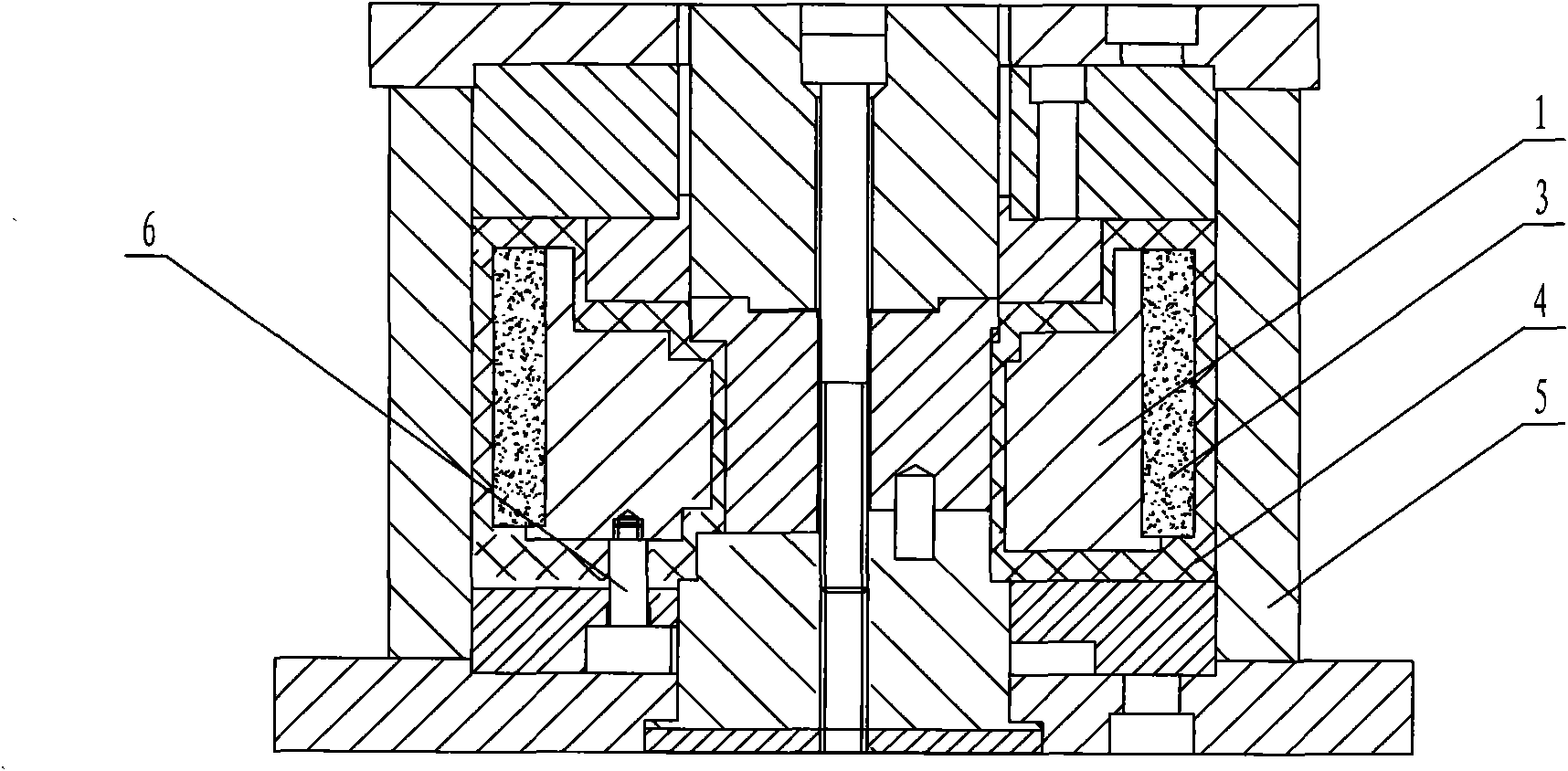
[0024] (b) Suspend the inner rotor base body 1 pasted with the magnetic material through the support column 6 provided at the bottom thereof, and put it into the mold 5;

[0025] (c) Add 920 grams of polyperfluoroethylene propylene (4) into the mold, put it into a heating furnace, heat it to 310°C ± 5°C, and keep it warm for 2 hours;

[0026] (d) Pre...


PUM


Abstract

The invention relates to a production process of an inner magnetic rotor of a magnetic drive pump, which comprises the following steps: uniformly coating glue liquid on the outer surface of a cleaned inner magnetic rotor body, pasting a magnetic material on the inner magnetic rotor body, curding for 2 hours at the temperature of 180 DEG C; sheathing the inner rotor body pasted with the magnetic material on a mould; adding fluorinated ethylene propylene (FEP) in the mould, heating to be 300-320 DEG C, keeping the temperature for 2-3h; pressing on a press with the pressure of 10-15MPa, and keeping the pressure for 30-40min and slowly cooling; processing a plug by using a tetrafluoroethane bar stock; and winding a tetrafluoroethane seal belt, coating acid-resisting antiseptic sealant, and twisting into a taper pipe thread of the pressed inner rotor. The invention ensures the whole encapsulating thereof through the pressing process and the sealing technology, does not leak, can improve the operational performance of high temperature of the magnetic rotor and transmitting performance of a strong corrodent, has the simple manufacture process and low production cost, and can completely ensure the operation performance of the inner magnetic rotor.

Description

technical field [0001] The invention relates to a production process of an inner magnetic rotor of a magnetic pump. Background technique [0002] In many industries, it is required to transport high-temperature and strong corrosive media. General metal corrosion-resistant chemical centrifugal pumps cannot meet the requirements. Special alloy pumps are expensive and uneconomical, so fluoroplastic-lined chemical centrifugal pumps or fluoroplastic-lined magnetic pumps are usually used. For pumps, the former uses an external mechanical seal that always leaks and pollutes the environment, while the latter has no leakage. However, since the internal magnetic rotor is made of plastics such as partial difluoride or polyether ketone, although the pressing process is simple, the encapsulation The inner magnetic rotor is safe and reliable, but it cannot withstand high temperature and strong corrosive media. It is also encapsulated with polyperfluoroethylene propylene (F46), but it is a...

Claims


Application Information

Patent Timeline
Patent Type & Authority Applications(China)
IPC IPC(8): F04D29/00
Inventor 任振林
Owner 鸿浩泵业有限公司
Why Eureka
Try Eureka