
3D heat radiating module type high-power LED illuminating device

A technology of LED lighting and heat dissipation module, which is applied to lighting devices, lighting device parts, lighting device cooling/heating devices, etc., can solve the problems of easily polluted total reflection surface, poor heat dissipation effect, and reduced reflection efficiency, etc. , to achieve the effect of good heat dissipation, flexible design and high light utilization rate

Inactive Publication Date: 2010-10-06
ZHEJIANG UNIV +1
View PDF11 Cites 7 Cited by
  • Summary
  • Abstract
  • Description
  • Claims
  • Application Information

AI Technical Summary

Problems solved by technology

Both have good light-gathering performance, but their light-gathering efficiency is low, generally 70-75%. In order to improve the light-gathering efficiency, both the reflector and the total reflection condenser lens need a larger volume, thus increasing the The volume of the lamp; at the same time, the mirror surface and the total reflection surface of the reflector are easily polluted, reducing the reflection efficiency
But because its illuminating device is connected by a connecting device, constitutes the whole structure, after illuminating device is assembled, can't arbitrarily change, if have LED damage to need to replace, assemble and disassemble and maintenance trouble; Suspended and fixed to work in a 3D heat dissipation environment, but the middle radiator still has the problem of poor heat dissipation because there is no air circulation channel in the vertical direction of the lamp body

Method used


Image

  • 3D heat radiating module type high-power LED illuminating device
  • 3D heat radiating module type high-power LED illuminating device
  • 3D heat radiating module type high-power LED illuminating device

Examples


Embodiment 1

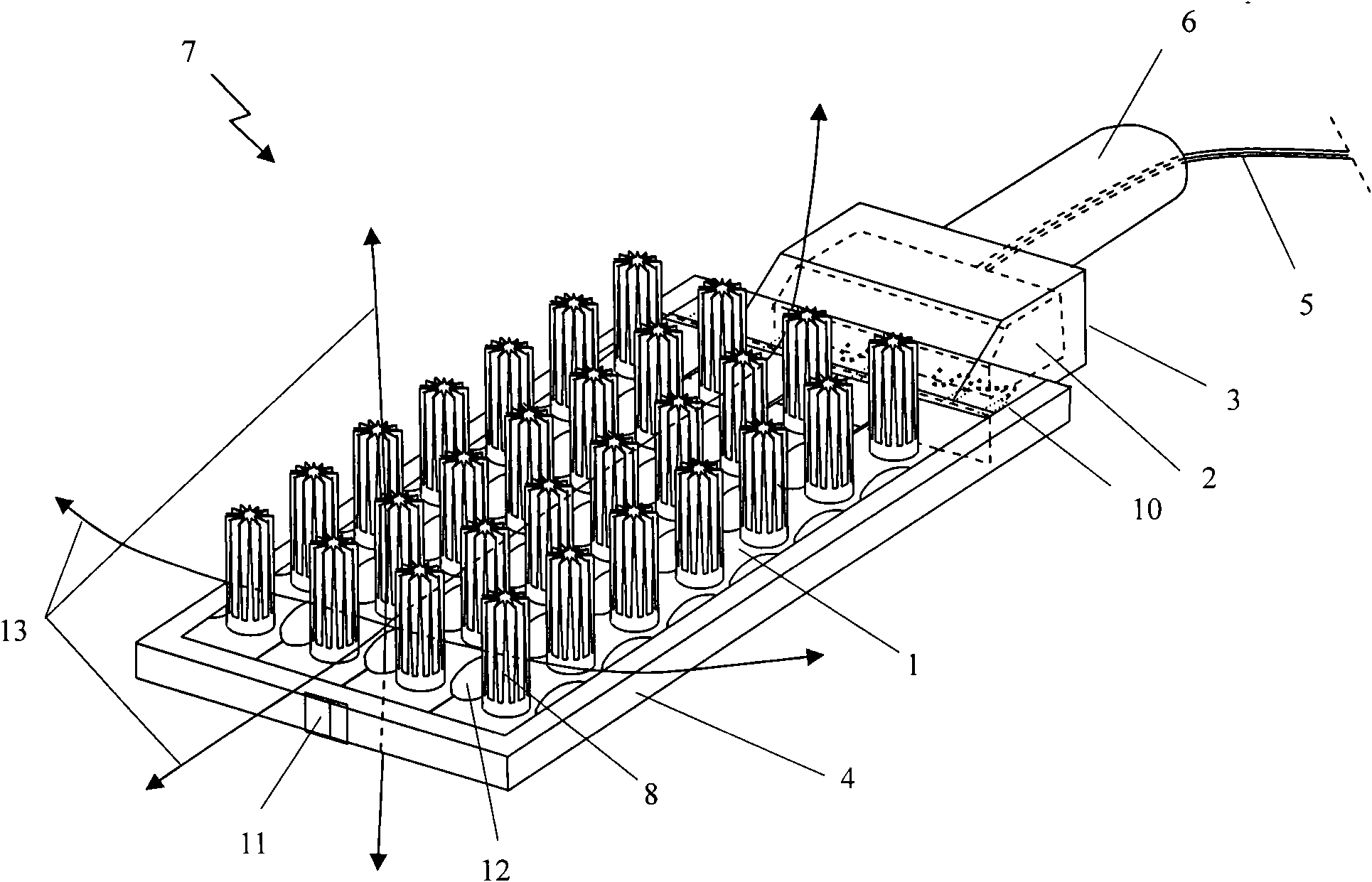
[0025] The present invention will be described in detail below in conjunction with the accompanying drawings. figure 1 It is a structural schematic diagram of an embodiment of the 3D heat dissipation modular high-power LED lighting device of the present invention. It includes: at least one detachable high-power LED module 1, at least one LED driver 2 and driver housing 3, a module fixing device 4, an electrical connection device 5 and a mechanical fixing device 6, which are connected to each other to form a lighting device 7 , figure 1 An example of a road light is shown.

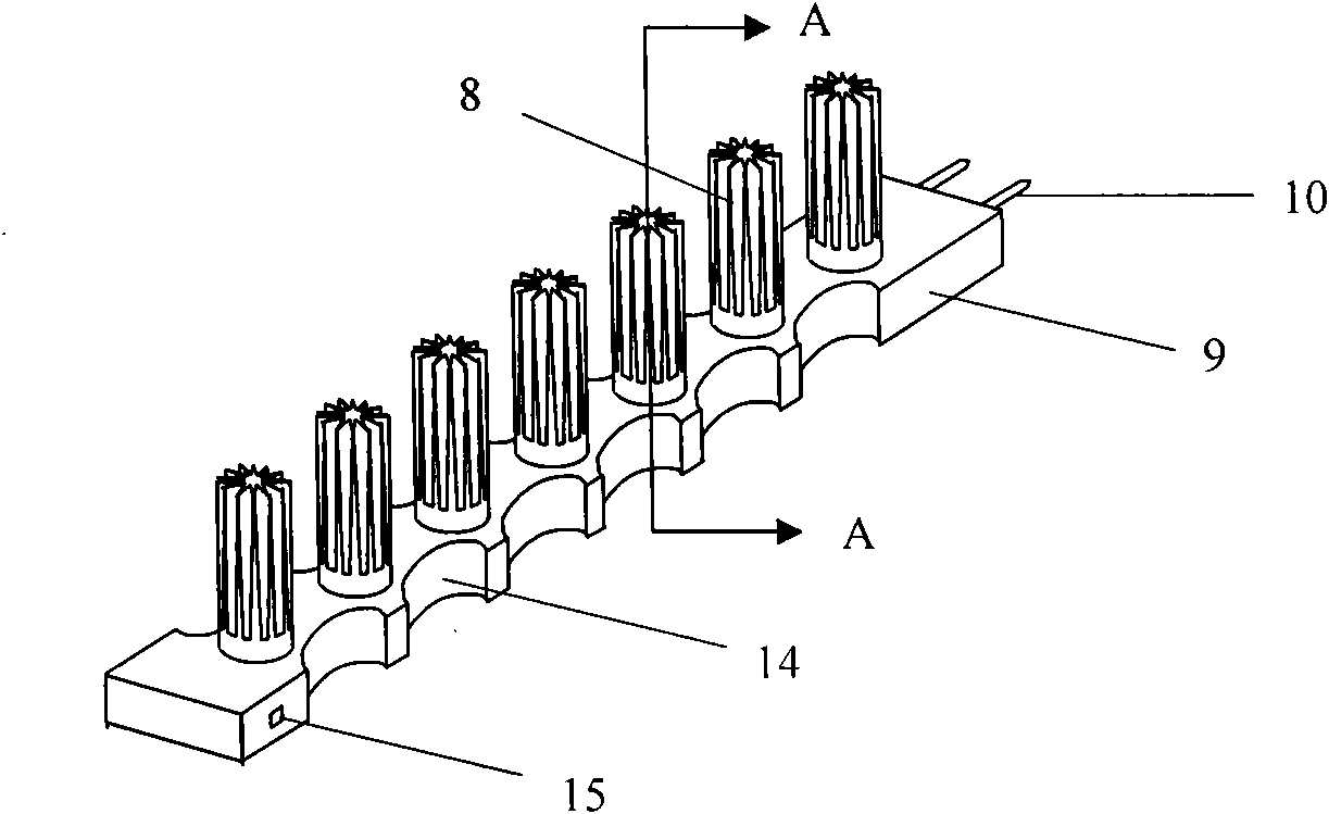
[0026] The LED module 1 such as figure 2 As shown, it includes at least one heat sink 8, a lamp body substrate 9, and an electrical connector 10. For the specific structure of the LED module, see image 3 and 4 shown.

[0027] Several LED modules 1 are spliced ​​together to form a lighting device, figure 1 Shown is an example composed of four modules 1; each module is fixed to each other by a module ...

Embodiment 2

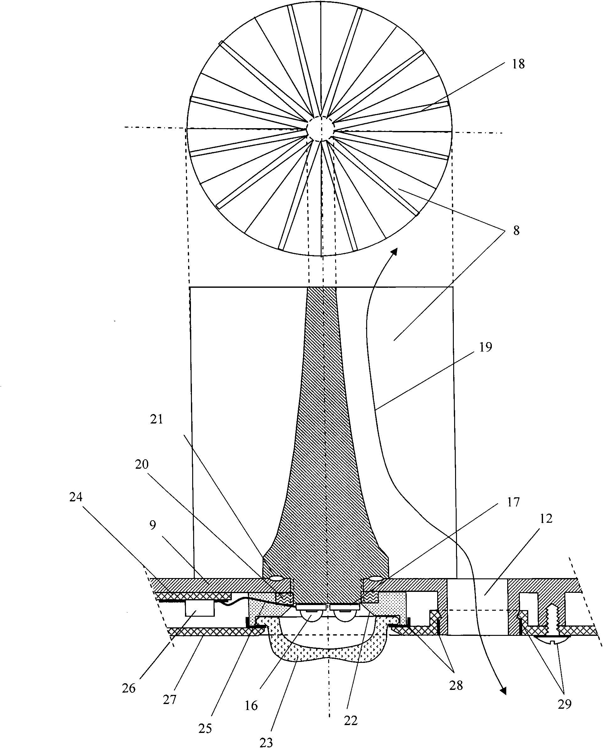
[0034] image 3 It is a partial section of an embodiment of the LED module of the present invention ( figure 2 A-A) Schematic diagram of the structure. In the figure, 16 is at least one high-power LED single tube, 8 is a radiator, and the heat sink of the LED is directly fixed on the radiator through a heat-conducting material 17; the radiator 8 has a series of cooling fins 18 parallel to the radiator axis; 9 Be lamp body substrate, 12 is the vent hole of lamp body substrate 9 sides, and 19 represents the air flow that circulates from vent hole; The fixing device 20 that radiator is used is fixed on lamp body substrate 9, and 21 is sealing rubber ring; LED 16 around There is a light reflector 22 for reflecting the light emitted by the LED to the side to the front; the front of the LED has a light distribution lens 23 .

[0035] Part of the loose blades 18 of the heat sink may be located above the air holes 12, so that the heat sink can dissipate heat better.

[0036] The h...

Embodiment 3

[0041] Figure 4 It is a partial section of another embodiment of the LED module of the present invention ( figure 2 A-A) Schematic diagram of the structure. It is characterized in that the radiator 8 and the lamp body substrate 9 are integrated; the LED is installed on the metal-based circuit board 30, and the metal-based circuit board 30 is connected to the radiator 8 through a heat-conducting material; lens.

[0042] For lamps that do not need to gather light, the light distribution lens 23 and the light reflection ring 22 may not be used; the light exit surface of the module 1 may have a light-transmitting plate or a curved light-transmitting cover to replace the sealing plate 27 . Figure 4 The meanings represented by other numbers in image 3 in the same.


PUM


Abstract

The invention relates to a 3D heat radiating module type high-power LED illuminating device which comprises at least one detachable high-power LED module, at least one LED driver, a module fixing device, an electrical connector and a mechanical connector which are mutually connected into the illuminating device. The illuminating device is characterized in that each detachable high-power LED module comprises at least one high-power LED single tube, at least one LED radiator, an electrical connector and a heat radiator fixing device, and all the LED modules are mutually connected and fixed through the module fixing device; all the heat radiators are mutually independently distributed, a lamp body between every two heat radiators is provided with a vent hole through which air can freely circulate, each heat radiator works in a 3D heat radiating environment, the heat radiating efficiency is high, each heat radiator is light and small, the weight of the heat radiator in the prior art is about 100-150g / W, the weight of the 3D heat radiating module type high-power LED illuminating device can be reduced to be below 30g / W, and the LED illuminating device has the advantages of arbitrary assembly of power size, convenient disassembly and maintenance, good heat radiation, fewer materials for the heat radiators, high illuminating efficiency, small and light lamps, low cost, long service life and the like and can be used for manufacturing illuminating lamps for shopping malls, roads, tunnels, stages, houses, offices and the like.

Description

technical field [0001] The invention relates to a semiconductor lighting device, in particular to a three-dimensional (3D) heat dissipation modular high-power LED lighting device. For home, office, shopping mall, road, tunnel, stage and other lighting. Background technique [0002] Existing high-power (also known as power type) LED single tubes cannot be used alone, and must be equipped with heat dissipation devices and good heat dissipation conditions to ensure that the LEDs work at normal operating temperatures. A high-power LED lighting fixture usually has several or even hundreds of high-power LED single tubes, and each high-power LED single tube has one or more LED chips. Thermally connected with the radiator, the large amount of heat generated by the LED is dissipated through the radiator. As a semiconductor device, LED is very sensitive to temperature. High temperature will greatly damage the luminous efficiency, service life, reliability and failure rate of LED. T...

Claims


Application Information

Patent Timeline
Patent Type & Authority Applications(China)
IPC IPC(8): F21S2/00F21V19/00F21V23/00F21V29/00F21V13/00F21V17/10F21V5/04F21V31/00F21Y101/02F21V29/503F21V29/70
Inventor 刘化斌葛世潮葛铁汉
Owner ZHEJIANG UNIV
Learn More