
Low-loss band-pass filter based on defected ground structure

A defect structure and band-pass filter technology, which is applied in waveguide devices, electrical components, circuits, etc., can solve problems such as the new filter structure of folded feeders that have not yet been seen, and achieve simplified processing complexity and good frequency selectivity , compact design effect

Inactive Publication Date: 2014-02-05
EAST CHINA JIAOTONG UNIVERSITY
View PDF2 Cites 0 Cited by
  • Summary
  • Abstract
  • Description
  • Claims
  • Application Information

AI Technical Summary

Problems solved by technology

However, in the existing technology, there is no new filter structure that combines folded feeder, T-shaped loading capacitor and "concave" defect ground structure (DGS)

Method used


Image

  • Low-loss band-pass filter based on defected ground structure
  • Low-loss band-pass filter based on defected ground structure
  • Low-loss band-pass filter based on defected ground structure

Examples


Embodiment Construction

[0023] The embodiment of the present invention is based on a low-loss bandpass filter with a defective ground structure. A zigzag feeder structure is adopted on a microstrip transmission line with 50 ohm impedance matching, and on this basis, a superstructure of a T-shaped loading capacitor and a "concave" are added. ” type defect ground structure (DGS) composition.

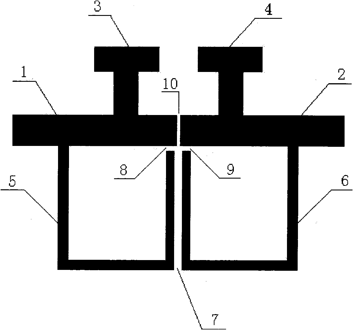
[0024] Figure 5 and Figure 6 They are respectively the overall size diagram of the upper layer of the low-loss bandpass filter based on the defect ground structure and the overall size diagram of the DGS layer according to the embodiment of the present invention.

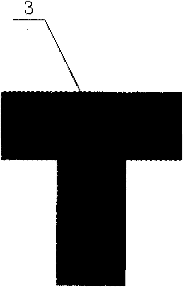
[0025] In the upper layer of the low-loss bandpass filter based on the defective ground structure in this embodiment, the size of the upper part of the T-shaped loading capacitor is 3.20mm×1.20mm, and the size of the lower part is 2.25mm×1.20mm. At 5.10mm at the end of the transmission line or output transmission line, the coupling gap between the ...


PUM


Abstract

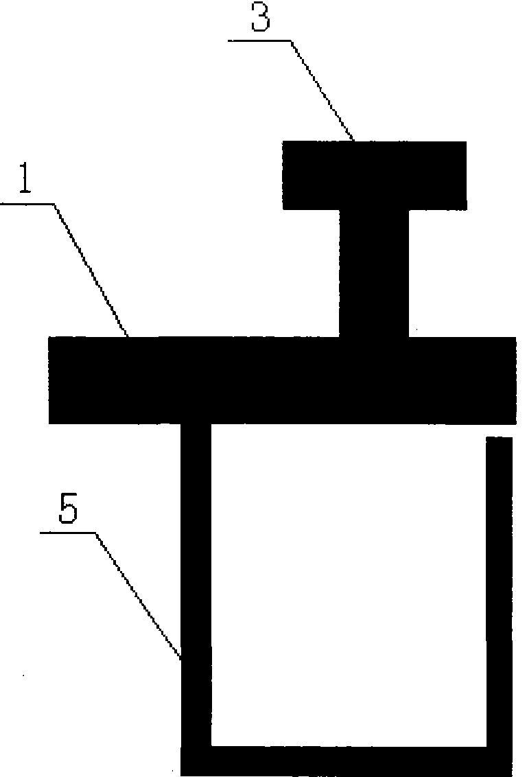
The invention discloses a low-loss band-pass filter based on a defected ground structure. A pair of folded type feeder structures (5) and (6) is adopted on micro-strip transmission lines matched at 50 ohmage impedance at the upper layer of the filter; a pair of T-type loading capacitors (3) and (4) is loaded; and a concave defected ground structure (DGS) is adopted on the horizontal plane of the filter. The folded type feeders (5) and (6) are coupled through a gap (7); and an input micro-strip transmission line (1) and an output micro-strip transmission line (2) are coupled through a gap (10). The invention adopts symmetric folded type feeder structures; the T-type loading capacitors and the concave DGS simplify the processing complexity and generate two transmission zeros around a passband; in addition, the concave DGS improves the inhibition of a filter rejection band which can inhibit the influence of surface waves and ultraharmonics, thereby obtaining better frequency selectivity. The invention has compact and tiny design, is easy to integrate, and can be used in a dense integrated circuit conveniently.

Description

technical field [0001] The invention relates to a low-loss band-pass filter with a defective ground structure, which belongs to the technical field of microwave transmission devices. Background technique [0002] With the continuous development of mobile communication, satellite communication, radar and wireless remote sensing technology, the system puts forward higher and higher requirements for the design of microwave and radio frequency filters in the front end of radio frequency transceiver. Due to the advantages of small size, relatively low processing complexity, light weight and easy integration, microstrip filters are widely used in circuits such as microwave integrated circuits (MICs). [0003] In the development process of satellite communication technology, the requirements for frequency band and bandwidth are getting higher and higher, and the design of broadband microstrip bandpass filter is also becoming more and more important, especially the S-band bandpass f...

Claims


Application Information

Patent Timeline
Patent Type & Authority Patents(China)
IPC IPC(8): H01P1/203
Inventor 刘媛媛黄德昌刘海文朱路官雪辉张跃进王传云张智翀文品高晓辉
Owner EAST CHINA JIAOTONG UNIVERSITY
Learn More