Data transmission equipment and method and data synchronization method

A data transmission and equipment technology, applied in the computer field, can solve the problems of high message format dependence, non-pluggable protocols, and difficulty, and achieve the effect of simplifying conversion and real-time sending and receiving, simplifying synchronous sending and receiving, and reducing system costs.

Inactive Publication Date: 2010-10-06
SHENZHEN LONG VISION
View PDF0 Cites 5 Cited by
  • Summary
  • Abstract
  • Description
  • Claims
  • Application Information

AI Technical Summary

Problems solved by technology

Because the protocol adaptation between systems needs to be processed before processing business logic, it results in low business processing efficiency; at the same time, the protocol is not pluggable. When a new protocol needs to be used to interact with external systems, the system needs to modify the interface. It is difficult to modify and develop;
[0006] 2. Message conversion is cumbersome
Due to the different message formats, it is necessary to implement the conversion of multiple message formats each time the business logic is processed, and the operation is cumbersome; in addition, the message format is highly dependent, and it needs to be modified when the format changes, and the steps are cumbersome;
[0007] 3. High system cost
The system realizes the message routing function by itself, which requires high coupling between the systems; because the routing is realized through a complex mesh structure, when the routing strategy changes, all related systems and interaction structures need to be modified, and the cost is relatively high. High, and it is not conducive to the data synchronization of the system

Method used


Image

  • Data transmission equipment and method and data synchronization method
  • Data transmission equipment and method and data synchronization method
  • Data transmission equipment and method and data synchronization method

Examples


Embodiment Construction

[0028] The following will clearly and completely describe the technical solutions in the embodiments of the present invention with reference to the accompanying drawings in the embodiments of the present invention. Obviously, the described embodiments are only some, not all, embodiments of the present invention. Based on the embodiments of the present invention, all other embodiments obtained by persons of ordinary skill in the art without creative efforts fall within the protection scope of the present invention.

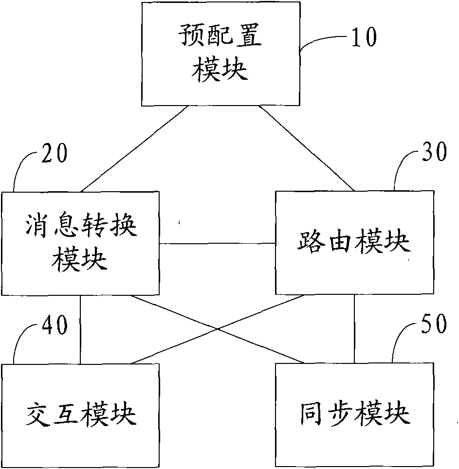
[0029] See figure 1 , is a schematic structural diagram of an embodiment of the data transmission device of the present invention; as figure 1 As shown, the data transmission device includes: a message conversion module 20 and a routing module 30 .

[0030] In a specific implementation, the data transmission device can be used as a public component and applied to a sending end, a receiving end, a client end, and a server end. For example: in a digital TV receivin...


PUM


Abstract

The invention discloses data transmission equipment, comprising a message conversion module and a route module, wherein, the message conversion module is used for constructing a first message supported by a preconfigured transmission protocol according to received parameter information, or for converting the received first message into a second message supported by service logic; and the route module is used for routing the first message constructed by the message conversion module to a message outlet to be transmitted to opposite equipment, or calling the service logic to respond the second message converted by the message conversion module. Correspondingly, the invention also discloses a data transmission method and a data synchronization method, can simplify message real-time receiving and transmission and synchronous receiving and transmission of asynchronous data, supports protocol plugging and various route strategies, decreases development difficulty and lowers system cost.

Description

technical field [0001] The invention relates to the field of computer technology, in particular to data transmission equipment, a method and a data synchronization method. Background technique [0002] A distributed system is a software system built on a computer network with a high degree of cohesion and transparency. With the widespread use of distributed systems, the interaction between systems is becoming more and more complex, and the difficulty of integration is also increasing. [0003] In the existing distributed system, each system, such as web (website) system, service (service) system, hessian (lightweight remote tool) system, etc., uses different protocols; when the system processes business logic, it first performs protocol The adaptation of the message, and then the conversion of the message is implemented by the business logic itself. The usual message content is XML (Extensible Markup Language, Extensible Markup Language). The business logic needs to parse t...

Claims


Application Information

Patent Timeline
Patent Type & Authority Applications(China)
IPC IPC(8): H04L29/08
CPCH04L67/327H04L67/63
Inventor 蔡振兴
Owner SHENZHEN LONG VISION
Why Eureka
Try Eureka