Pneumatic tire for motor-bicycle
A technology for motorized two-wheeled vehicles and pneumatic tires, which is applied to the reinforcement layer of motor vehicles, pneumatic tires, motorcycle tires, etc., can solve the problem of inability to apply driving force, etc. The effect of improving traction performance
- Summary
- Abstract
- Description
- Claims
- Application Information
AI Technical Summary
Problems solved by technology
Method used
Image

Examples
Embodiment 1~3
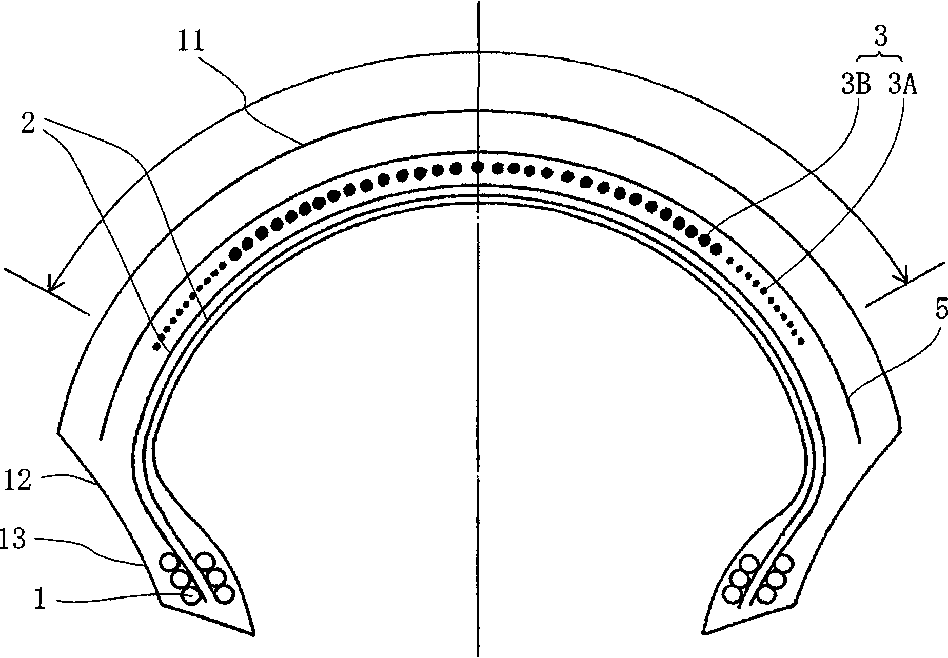
[0066] According to the following conditions, tire size 190 / 50ZR17 was manufactured with the following figure 1 A pneumatic tire for motorcycles having a cross-sectional structure as shown. Each test tire had a carcass ply composed of two carcass plies extending toroidally between a pair of bead cores. Here, nylon fibers are used for the carcass ply. The angle of the two-ply carcass is the radial direction (the angle with respect to the equator direction is 90 degrees). In addition, as shown in the drawing, the ends of the respective carcass plies are pinched and locked by bead wires from both sides of the bead portion.
[0067] In addition, a spiral belt layer is disposed outside the carcass in the tire radial direction. In Example 1, the both end regions of the spiral belt layer are layers made of twisted nylon cords, and the central region is made of twisted aramid (trade name: Kevlar). ), hereinafter, in this embodiment, the trade name "Kevlar" is also sometimes used ...
Embodiment 4
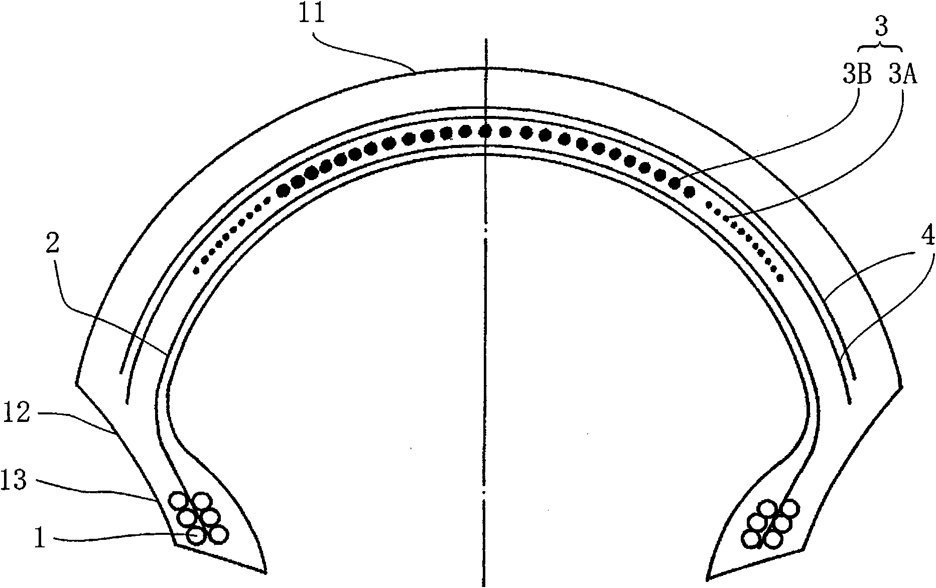
[0072] According to the following conditions, a figure 2A pneumatic tire for motorcycles having a cross-sectional structure as shown. The carcass ply is one layer, and is arranged in the radial direction (the angle with respect to the equator direction is 90 degrees). In addition, on the outside of the spiral belt in the tire radial direction, two belt intersecting layers were arranged instead of a belt reinforcing layer. The belt intersecting layer was formed by arranging cords having a diameter of 0.5 mm twisted with aramid fibers at a beating density of 50 threads / 50 mm. The angle of the belt intersecting layers is ±60 degrees with respect to the tire direction, and they cross each other. The arrangement width of the belt intersecting layers was 250 mm for the first layer (inner side) and 230 mm for the second layer (outer side).
Embodiment 5
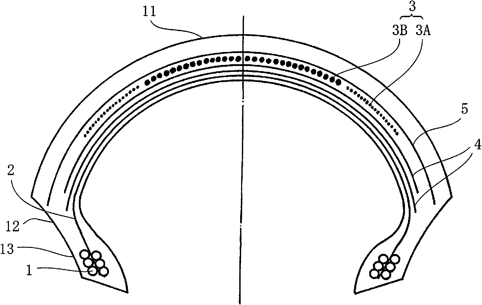
[0074] According to the following conditions, a image 3 A pneumatic tire for motorcycles having a cross-sectional structure as shown. The carcass ply is one layer, and is arranged in the radial direction (the angle with respect to the equator direction is 90 degrees). In addition, two belt intersecting layers similar to those in Example 4 were arranged on the inner side of the spiral belt in the tire radial direction. Therefore, in this case, the belt intersecting layers exist immediately outside the carcass, and the spiral belt layer exists further outside the belt intersecting layers. In addition, on the outer side of the spiral belt layer in the tire radial direction, a belt reinforcement layer made of aramid fiber having an angle of 90 degrees with respect to the tire circumferential direction was arranged in the same manner as in Example 1. The tread is located on the outer side of the belt reinforcement layer.
PUM
 Abstract
Description
Claims
Application Information
 - R&D
- Intellectual Property
- Life Sciences
- Materials
- Tech Scout
- Unparalleled Data Quality
- Higher Quality Content
- 60% Fewer Hallucinations
Browse by: Latest US Patents, China's latest patents, Technical Efficacy Thesaurus, Application Domain, Technology Topic, Popular Technical Reports.
© 2025 PatSnap. All rights reserved.Legal|Privacy policy|Modern Slavery Act Transparency Statement|Sitemap|About US| Contact US: help@patsnap.com