
Construction method of erecting prestressed concrete beam on river

A technology of prefabricated concrete and construction methods, applied in the direction of erection/assembly of bridges, bridges, bridge construction, etc., can solve the problems of high cost of hoisting, and achieve the effect of strong applicability

Inactive Publication Date: 2010-10-13
SHANGHAI HIGHWAY BRIDGE (GRP) CO LTD
View PDF3 Cites 11 Cited by
  • Summary
  • Abstract
  • Description
  • Claims
  • Application Information

AI Technical Summary

Problems solved by technology

Taking a 30-meter small box girder as an example, a crawler crane of at least 300 tons and additional counterweights are required to complete the erection, and the cost of hoisting is very expensive

Method used


Image

  • Construction method of erecting prestressed concrete beam on river
  • Construction method of erecting prestressed concrete beam on river
  • Construction method of erecting prestressed concrete beam on river

Examples


Embodiment 1

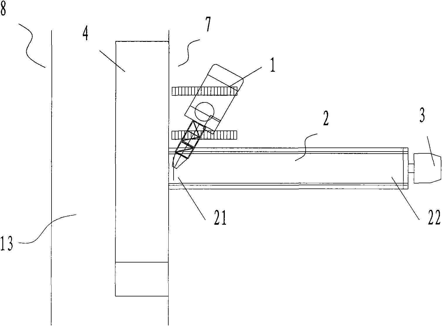
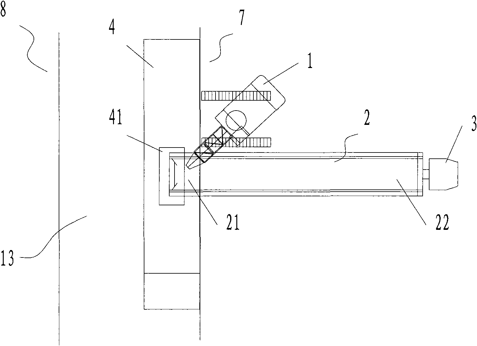
[0040] Embodiment 1: A construction method for erecting precast concrete beams across a river, comprising the following steps:

[0041] 1) park the first crawler crane 1 and the second crawler crane 6 on the first river bank 7 and the second river bank 8 respectively; the precast concrete beam 2 is loaded by the transport vehicle 3; The rear part 21 of the concrete beam 2 reaches the bank of the first river bank 7, and the precast concrete beam 2 is perpendicular to the river 13, as figure 1 As shown; in other specific embodiments, according to the specific conditions of the construction site, when the rear portion 21 of the precast concrete beam 2 reaches the river bank, the precast concrete beam 2 can also be substantially perpendicular to the river 13 to achieve basically the same effect.

[0042] 2) The rear portion of the precast concrete beam 2 is hoisted on the barge 4 near the bank of the first river bank 7: the first crawler crane 1 lifts the rear portion 21 of the pr...

Embodiment 2

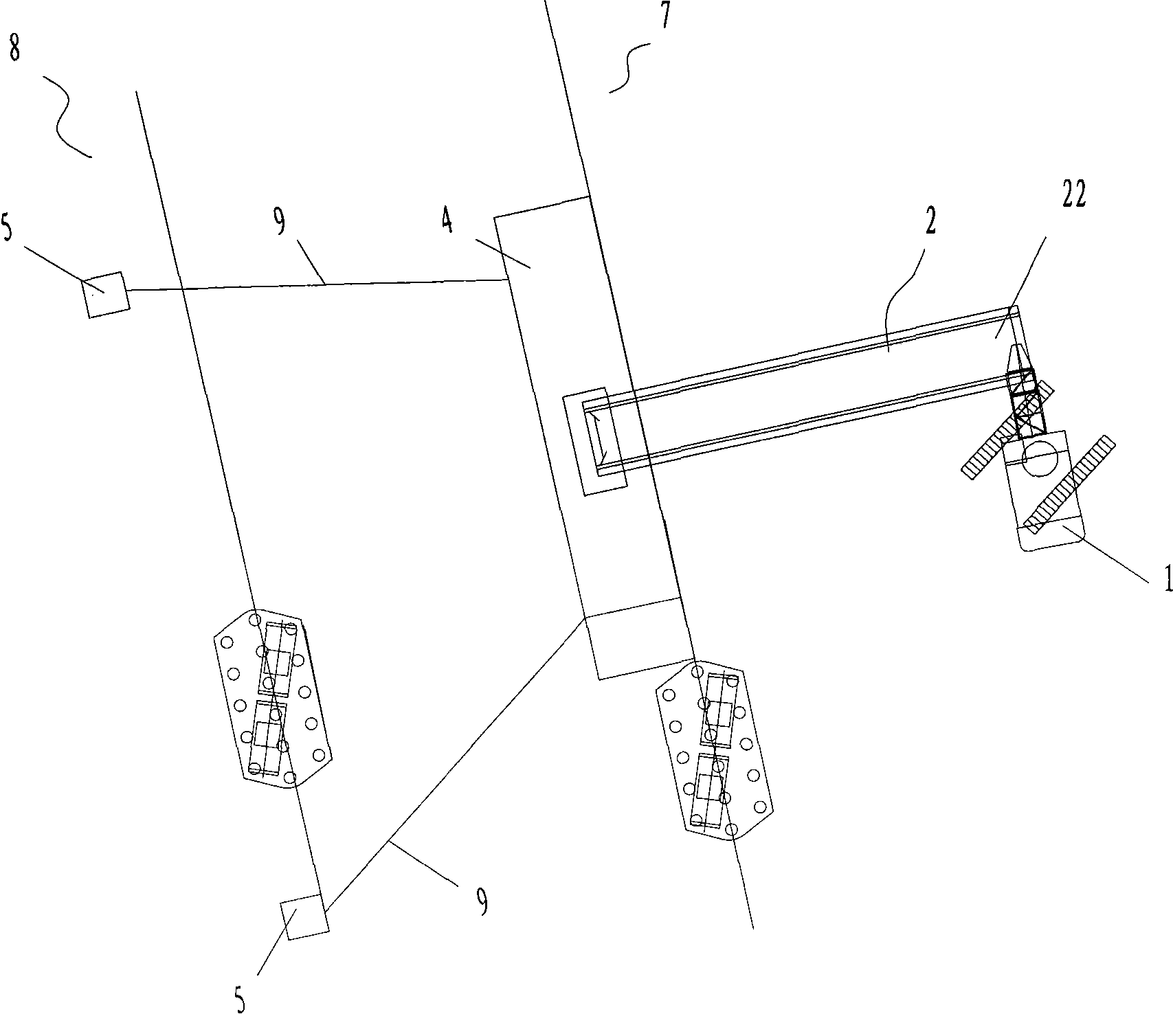
[0048] Embodiment 2: as Figure 7 As shown, the construction method of this embodiment is basically the same as that of Embodiment 1, the difference is that in step 3), during the process of moving the barge 4 to the second river bank 8, a steel wire rope 10 and a hoist are also arranged on the first river bank 7 11 is connected with barge 4, so the motion process of barge 4 is more stable.

[0049] Other steps in this embodiment are the same as in Embodiment 1.

Embodiment 3

[0050] Embodiment 3: as Figure 8 As shown, the construction method of the present embodiment and embodiment 2 is basically the same, the difference is: in step 1), the third crawler crane 12 is provided at the first river bank 7 places; the first crawler crane 1 lifts the precast concrete The front part 22 of the beam 2, the third crawler crane 12 lifts the rear part 21 of the precast concrete beam 2; shore. Therefore, when the conditions on the river bank do not meet the conditions for passing or reversing transport vehicles, the rear part of the precast concrete beam 2 can still reach the bank of the first river bank 7 .

[0051] Other steps in this embodiment are the same as in Embodiment 2.


PUM


Abstract

The invention discloses a construction method of erecting a prestressed concrete beam on river. The method comprises the following steps that: (1) a first crane and a second crane are respectively parked at the first river bank and the second river bank and the back of the prestressed concrete beam reaches the bank of the first river bank, (2) the back of the prestressed concrete beam is suspended and placed on a barge close to the bank of the first river bank, (3) the barge moves to the second river bank and in the process, the first crane hoists the front of the prestressed concrete beam and moves towards the second river bank along with the movement of the prestressed concrete beam, (4) the second crane hoists the back of the prestressed concrete beam placed on the barge and consequently the first crane and the second crane hoist and place the prestressed concrete beam on a bridge stand column. The invention uses two or more than two cranes and barges of medium tonnage together, therefore the invention is economical, practical and high efficient.

Description

technical field [0001] The invention relates to a bridge erecting method, in particular to a construction method for erecting prefabricated concrete beams across a river. Background technique [0002] As people's requirements for the environment are getting higher and higher, most modern urban bridges use prefabricated concrete beams, that is, the whole or several beams are poured into shape in the factory, transported to the site by heavy-duty transport vehicles, and then lifted by lifting equipment Hoist it across the river into place. For precast concrete beams, the conventional erection methods are as follows: [0003] 1) Bracket method: Dense temporary buttresses are built in the river, a platform is built on the buttresses, and then the prefabricated concrete beams are pushed or pulled from the platforms to cross the river, and finally the platform and the buttresses are dismantled. [0004] When using the support method, it is necessary to drive a lot of steel pipe ...

Claims


Application Information

Patent Timeline
IPC IPC(8): E01D21/06E01D101/24
Inventor 刘伟俊黄超
Owner SHANGHAI HIGHWAY BRIDGE (GRP) CO LTD
Learn More