
Phase modulation stepped array micro-spectrograph

A miniature spectrometer and phase modulation technology, applied in interference spectroscopy, instruments, spectrometry/spectrophotometry/monochromator, etc., can solve the problems of narrow measurement bandwidth, high production cost and low resolution, etc. Achieve the effect of wide spectral measurement range, low production cost and high resolution

Inactive Publication Date: 2010-10-13
NANJING FANGYUAN GLOBAL DISPLAY TECH
View PDF0 Cites 19 Cited by
  • Summary
  • Abstract
  • Description
  • Claims
  • Application Information

AI Technical Summary

Problems solved by technology

[0004] Technical problem: The purpose of the present invention is to provide a phase-modulated stepped array micro-spectrometer, which solves the technical problems in the background technology such as large volume, sensitivity to vibration, high production cost, low resolution, and narrow measurement frequency bandwidth.

Method used


Image

  • Phase modulation stepped array micro-spectrograph
  • Phase modulation stepped array micro-spectrograph
  • Phase modulation stepped array micro-spectrograph

Examples


Embodiment Construction

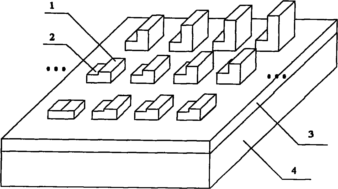
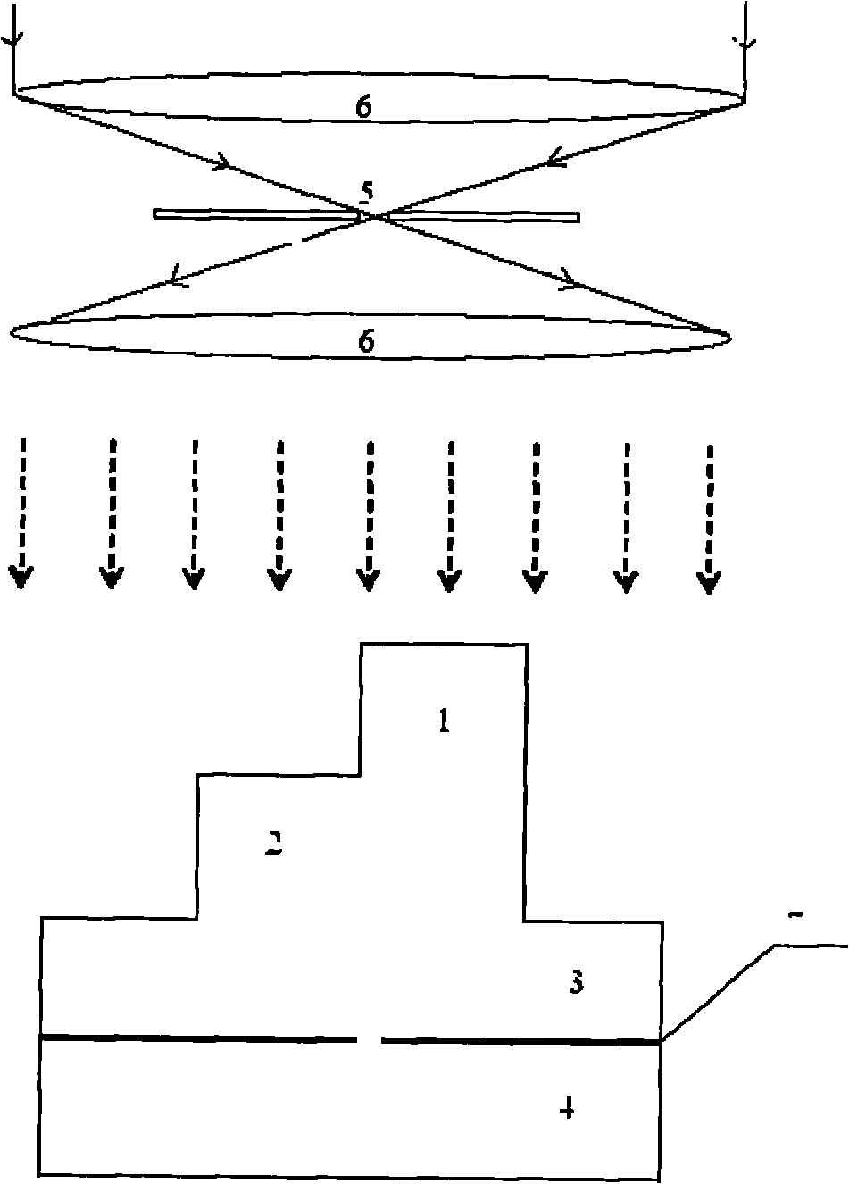
[0026] The spectrometer of the present invention comprises a two-dimensional array of micro-interferometers built on the upper surface of the substrate 3, each micro-interferometer is provided with a first step 1, and the height of the first step 1 is different in different micro-interferometers. The lower surface is provided with CCD4, and there is a shield 7 between the substrate 3 and the CCD4; the shield 7 covers most of the CCD facets, but there is a light-transmitting hole on the shield 7 below each micro-interferometer, through which The aperture of the light hole is smaller than the minimum wavelength of the incident light wave that can be detected by the CCD4, and the light transmission hole is located at any position below the first step. In order to improve the sensitivity of the entire device, the light transmission hole is located directly below the edge of the first step 1, if The step width is within two incident light wavelengths, and the light transmission hole...


PUM


Abstract

The invention relates to a phase modulation stepped array micro-spectrograph which comprises a micro-interferometer two-dimensional array constructed on the upper surface of a substrate (3). Each micro interferometer is provided with a first step (1); the first steps (1) have different heights in different micro-interferometers; the lower surface of the substrate (3) is provided with a CCD (4), and a layer of shielding objects (7) is arranged between the substrate (3) and the CCD (4); most of CCD surface elements are shielded by the shielding objects (7), light holes are left in the shielding objects (7) below each micro interferometer, the diameter of each light hole is smaller than the minimum wavelength of an incident light wave detected by the CCD (4), the width of the first step and the wavelength of the incident light wave are in the same magnitude, the maximum height of the first step also is the wavelength magnitude of the incident light wave, two confocal lenses (6) are arranged above the micro-interferometer two-dimensional array, an a light shielding plate at the focal point between the two confocal lenses (6) is provided with small holes (5). The invention solves the technical problems of large volume, vibration sensitivity, high manufacturing cost, low resolution, narrow measured bandwidth and the like.

Description

technical field [0001] The invention relates to a spectrum measurement device, in particular to a portable real-time detection spectrum measurement device. Background technique [0002] A spectrometer is an important analytical instrument that analyzes the composition and content of a substance by obtaining the spectral signal of the research substance. The application of the spectrometer has been expanded with every development of the spectrometer, and it has been widely used in almost all analytical fields. Such as modern scientific experiments, biological research, medical and medical research, industrial and agricultural production, national defense, astronomical observation, etc. Specifically, in geological exploration, the inspection of various material components and their contents in ores; in the metallurgical industry, the analysis of C, P, and S in molten steel; in the food industry. Analysis of harmful metal impurities and vitamins in food; in biology, medicine, ...

Claims


Application Information

Patent Timeline
Patent Type & Authority Applications(China)
IPC IPC(8): G01J3/45G01J3/02
Inventor 何浩培杨涛李千秋黄维蔡潮盛
Owner NANJING FANGYUAN GLOBAL DISPLAY TECH
Learn More