Equal-pressure virtual isolation check valve sealing test method and equipment

A test method and technology of test equipment, applied in the field of detection, can solve the problems of difficult isolation, small space, and inability to quantify

Active Publication Date: 2010-10-13
北京冶核技术发展有限责任公司
View PDF5 Cites 27 Cited by
  • Summary
  • Abstract
  • Description
  • Claims
  • Application Information

AI Technical Summary

Problems solved by technology

The disadvantages are: the structure is relatively complicated, and because of the small space in the valve body, the installation is difficult and takes a lot of time, so it is not suitable for use in places with high radioactive doses
[0005] Due to the certain weight of the test sealing plug, its lower part is well sealed with the inner wall of the pipeline, while the upper part has a large gap, which is easy to leak, and even causes the upper part of the sealing ring to rupture; the valve outlet pipe and the inner wall of the process pipeline are due to processing, welding, fluid erosion, corrosion, etc. The surface is rough, uneven, smooth, and often uneven due to many reasons.
Therefore, it is difficult to completely isolate by conventional methods such as mechanical or soft seals, and only by thoroughly isolating the outlet pipe of the check valve can the tightness of the valve be accurately tested
Therefore, the test method of temporary sealing and isolation of mechanical sealing plug cannot accurately obtain the sealing parameters of the valve.
[0006] 3. Using water as the test medium, the disadvantage of using the pressure drop method to test the tightness of the valve is that it cannot be quantified

Method used


Image

  • Equal-pressure virtual isolation check valve sealing test method and equipment
  • Equal-pressure virtual isolation check valve sealing test method and equipment

Examples


Embodiment Construction

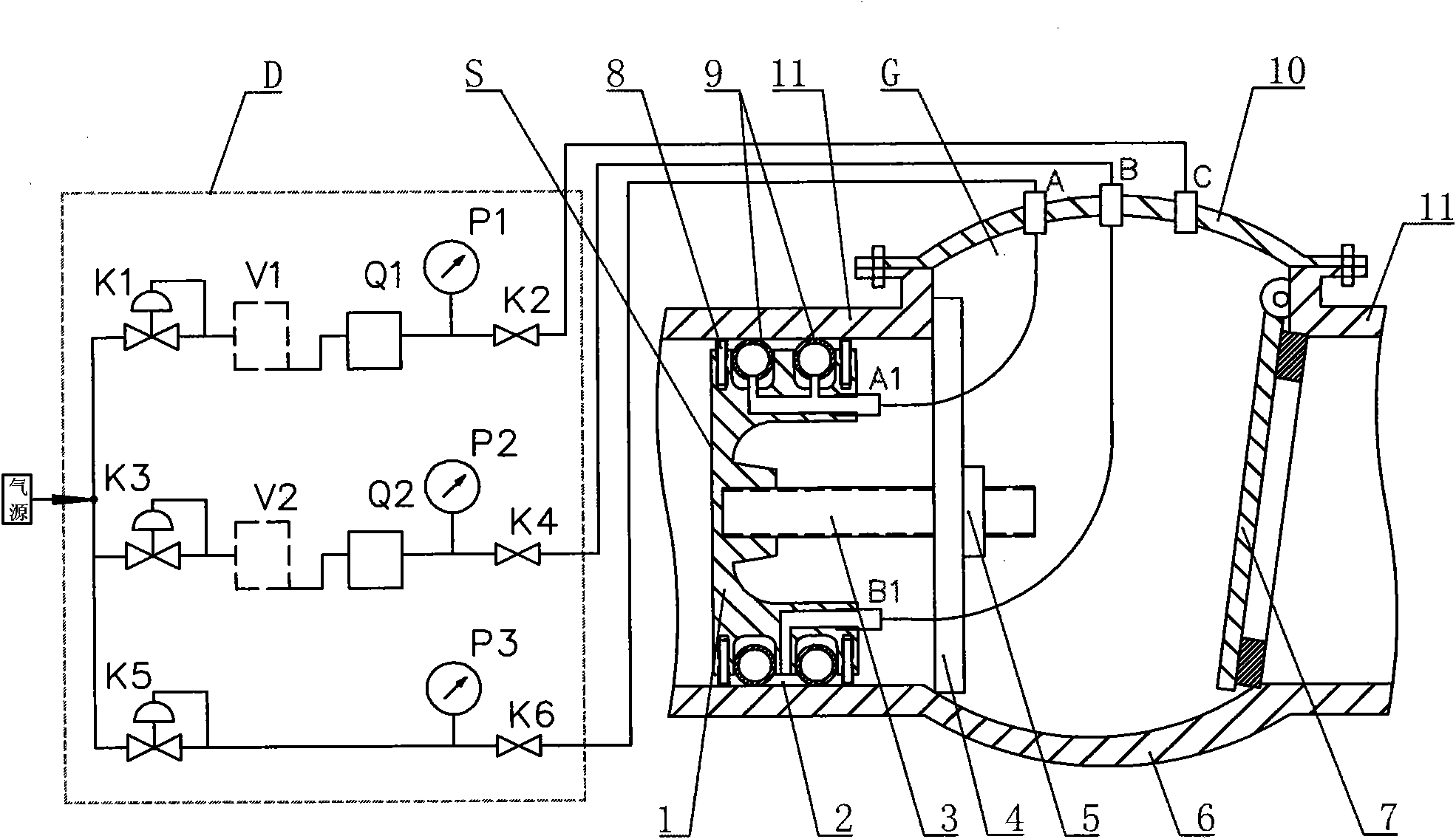
[0021] figure 1 In the figure, the left half is the leak detector D, and the right half is the isobaric isolation component S that realizes isobaric virtual isolation.

[0022] Leak detector D shares the same air source and has three inputs:

[0023] The first route consists of regulating valve K1, container V1, multi-range flowmeter Q1, pressure gauge P1 and shut-off valve K2. It is used for filling the valve cavity and measuring the leakage rate;

[0024] The second route consists of regulating valve K3, container V2, flow meter Q2, pressure gauge P2 and shut-off valve K4. It is used for pressurizing the space 2 between the double sealing rings 9 and measuring the leakage rate;

[0025] The third route consists of regulating valve K5, pressure gauge P3 and cut-off valve K6. Used to pressurize the seal ring.

[0026] The check valve G to be tested consists of a valve body 6, a valve plate 7, a valve cover 10, a valve inlet and outlet pipe 11, and three test joints A (sea...


PUM


Abstract

The invention relates to equal-pressure virtual isolation check valve sealing test method and equipment, which are realized through an equal-pressure virtual isolation sealing plug and a leak detector by the following steps of: firstly arranging the equal-pressure virtual isolation sealing plug in an outlet pipe of a tested check valve; filling pressure in the sealing ring and the annular space of the sealing plug through the test fluid of the leak detector, and carrying out virtual isolation on the outlet pipe of the tested check valve through a formed equal-pressure ring; then carrying out fluid filling on a cavity between the equal-pressure virtual isolation sealing plug and a valve plate in the tested check valve through the leak detector, and keeping the pressure in the cavity of the tested check valve to be constant; and subsequently detecting the supplemented flow value of the fluid, i.e. the leakage ratio of the valve, wherein the test fluid not only can be gas, but also can be a liquid. The invention has the characteristics of accurate and reliable testing result, short working time of testing personnel in a high-dose region, low acceptable dose and less time for installing an equal-pressure isolation plug body 1. A low-pressure sealing test is adopted for test pressure, and the test pressure is generally consistent with the test pressure of a nuclear power plant containment.

Description

technical field [0001] The invention belongs to detection technology, and relates to a method for testing the sealing performance of an isobaric virtual isolation check valve and experimental equipment for realizing the method. It is suitable for testing the sealing performance of valves, and is especially suitable for the check valve installed in the process system of a nuclear power plant by welding. Valve tightness test. Background technique [0002] It is a mature technology to test the tightness of the check valve on the bench, but there are certain difficulties and defects in the tightness test of the check valve installed in the process system: [0003] 1. Ice plug sealing and isolation: The sealing test is carried out after the outlet pipe of the check valve is blocked with ice plug. The disadvantage is that the process is more complicated, the work efficiency is low, and the valve body under test may be damaged. [0004] 2. Temporary sealing and isolation of the me...

Claims


Application Information

Patent Timeline
Patent Type & Authority Applications(China)
IPC IPC(8): G01M3/28
Inventor 蒋坚毅王煊郭红晓李安明秦传豪孙颢房厦周文权
Owner 北京冶核技术发展有限责任公司
Why Eureka
Try Eureka