Complementary type modularization permanent-magnetism linear motor and motor die set formed by same

A permanent magnet linear motor, modular technology, applied in the direction of electric components, electrical components, electromechanical devices, etc., can solve the problem of not taking into account the complementarity of each phase winding and structure, the asymmetry of the positive and negative half cycles of the magnetic flux, and the asymmetry of the positive and negative half cycles. Problems such as symmetry, to achieve the effect of saving permanent magnet materials, small thrust fluctuations, and strong output thrust

Inactive Publication Date: 2010-10-13
HAIAN KINGLORD PHOTOELECTRIC CO LTD +1
View PDF1 Cites 33 Cited by
  • Summary
  • Abstract
  • Description
  • Claims
  • Application Information

AI Technical Summary

Problems solved by technology

However, the positive and negative half cycles of the magnetic flux of the end phase windings of the traditional flux switching linear motor are asymmetrical, which causes the imbalance of the opposite potentials
The traditional modular f

Method used


Image

  • Complementary type modularization permanent-magnetism linear motor and motor die set formed by same
  • Complementary type modularization permanent-magnetism linear motor and motor die set formed by same
  • Complementary type modularization permanent-magnetism linear motor and motor die set formed by same

Examples


Embodiment 1

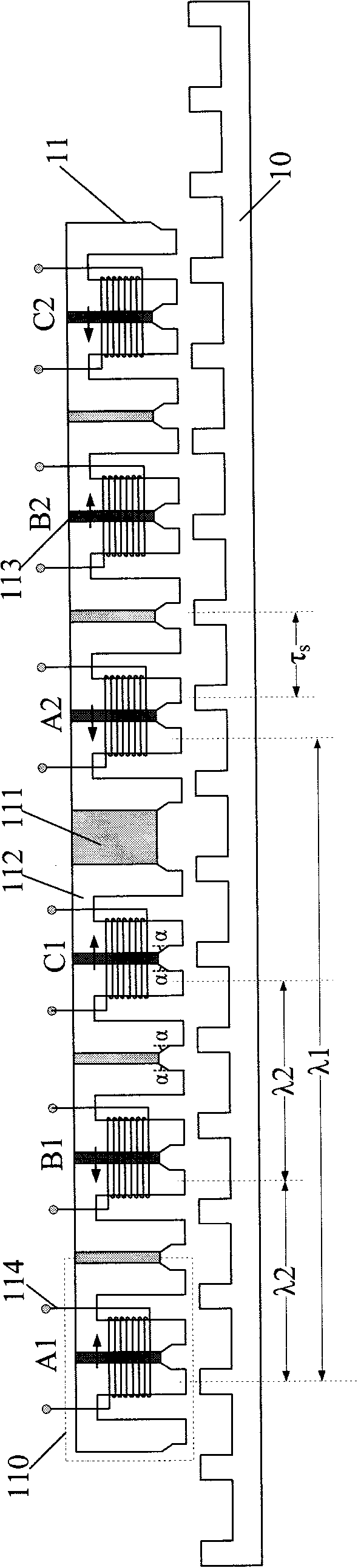
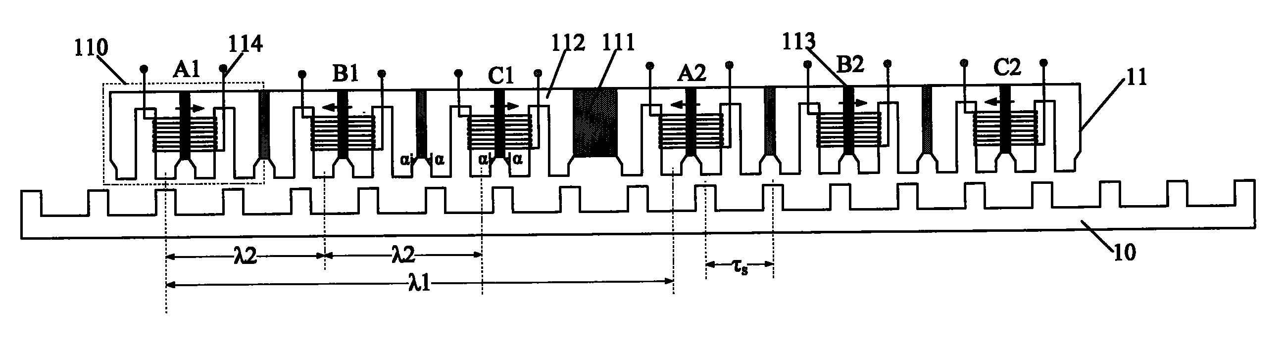
[0021] like figure 1 As shown, the complementary modular permanent magnet linear motor 1 provided by the present invention is composed of a stator 10 and a mover 11 with an air gap between them. As shown in the figure, both the stator 10 and the mover 11 adopt a salient pole structure. Wherein, there is neither permanent magnet nor winding on the stator 10, but only magnetically permeable material.

[0022] The mover 11 is composed of 2m E-shaped modules 110, and a non-magnetic material 111 is filled between two adjacent E-shaped modules. In this embodiment, m=3, that is, the motor has three phases A, B and C shown in the figure. Furthermore, each E-shaped module 110 is composed of two U-shaped magnetic permeable teeth 112 and a permanent magnet 113 . The concentrated winding 114 is placed in the two slots of the E-shaped module 110 , and covers the permanent magnet 113 and the U-shaped magnetic permeable teeth 112 adjacent thereto.

[0023] In this embodiment, there are t...

Embodiment 2

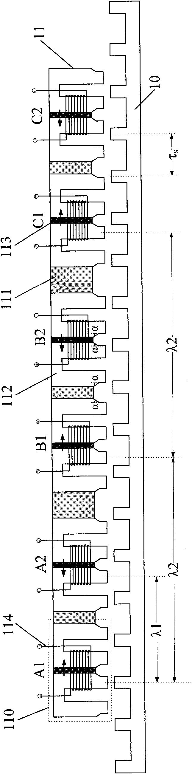
[0030] like figure 2 As shown, the difference between the complementary modular permanent magnet linear motor in this embodiment and that in Embodiment 1 lies in the adjacent placement of the two E-type modules where the first concentrated winding and the second concentrated winding of phase A are located. The displacement of the two E-type modules relative to the stator is also λ 1 =(n±1 / 2)τ s , forming a complementary symmetric structure. Phase B and Phase C have the same structure as Phase A. The displacement of the E-type module where the A, B, and C three-phase windings are located relative to the stator is λ 2 =(j±1 / m)τ s , where τ s is the stator pole pitch, n and j are both positive integers. Other structures and characteristics are the same as in Example 1.


PUM


Abstract

The invention provides a complementary type modularization permanent-magnetism linear motor and a motor die set formed by the same. The permanent-magnetism linear motor comprises a stator and a runner. The stator and the runner are both in a salient pole structure, and an air gap exists between the stator and the runner. The runner comprises 2m E-type modules, wherein m is the phase number of the motor. A non-magnetic material is filled between the two adjacent E-type modules. Each E-type module comprises 2 U-type magnetic teeth and a permanent magnet arranged between the U-type magnetic teeth, wherein concentrated windings are arranged in the grooves of the E-type modules and sleeve the permanent magnets. The relative displacement between the two in-phase E-type modules is lambda 1=(n+/-1/2) Tau s, the relative displacement between the two out-of-phase E type modules is lambda 2=(j+/-1/m) Tau s, Tau s is the polar distance of the stator, and n and j are both positive integers. Each phase of windings of the motor has symmetrical complementarity, and the counter potential of the motor has symmetrical waveform and is a sine. Moreover, the complementarity of the structure is greatly lowered, and even the positioning force of the motor is counteracted.

Description

technical field [0001] The invention relates to the technical field of motor manufacture, and in particular relates to a permanent magnet linear motor with complementary modular winding and structure and a motor module composed of it. Background technique [0002] The motor is the main part of the transmission system, and a reasonable selection of the motor can improve the performance and efficiency of the entire system. In linear applications, traditional rotary motors require certain mechanical transmission components to convert rotary motion into linear motion. This brings many problems, such as bulky system, increased weight, high noise, increased maintenance costs, and in rail transit applications, wheel-rail slippage will occur if the speed is too high. Therefore, the technical means of replacing the rotary motor with a linear motor can overcome the above-mentioned shortcomings of the rotary motor in this application and improve the efficiency of the entire system. ...

Claims


Application Information

Patent Timeline
IPC IPC(8): H02K41/03
Inventor 程明曹瑞武花为赵文祥
Owner HAIAN KINGLORD PHOTOELECTRIC CO LTD
Why Eureka
Try Eureka