

Direct-current booster circuit suitable for micro power inversion
A DC boost circuit and micro power technology, applied in the direction of converting DC power input to DC power output, output power conversion devices, electrical components, etc., can solve the problems of poor waveform quality, difficult debugging, complicated circuits, etc. Achieve the effect of low production cost, high conversion efficiency and simple circuit structure
Inactive Publication Date: 2010-10-13
BEIJING JIAOTONG UNIV
View PDF2 Cites 8 Cited by
- Summary
- Abstract
- Description
- Claims
- Application Information
AI Technical Summary
Problems solved by technology
Traditional inverter devices generally adopt the method of inverting first and then boosting voltage, which has high cost, complex circuit, difficult debugging and poor waveform quality
Method used
View moreImage
Smart ImageViewing Examples

Examples
Embodiment Construction
Login to View More PUM
 Abstract
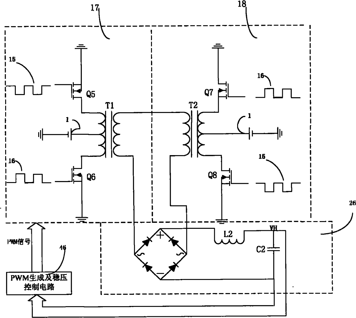
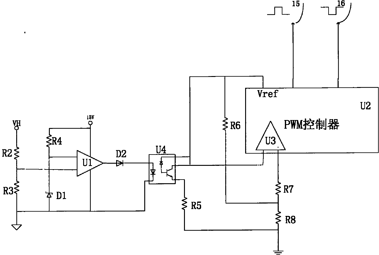
The invention relates to a direct-current booster circuit suitable for micro power inversion, which comprises two symmetrical push-pull circuits, a rectifier and filter circuit and a PWM generating and voltage stabilizing control circuit. Output results of the two symmetrical push-pull circuits are superposed to generate 380V alternating current; the rectifier and filter circuit rectifies and filters the 380V alternating current to generate 330V direct current; and a second resistor (R2) and a third resistor (R3) in the PWM generating and voltage stabilizing control circuit perform voltage partition on the 330V direct current generated by the rectifier and filter circuit, the partial voltage is compared with a reference voltage stabilized by a voltage stabilizing tube (D1) through a comparator (U1) to output high and low levels, the high and low levels are added to the reverse input end of a differential amplifier (U3) of a PWM controller (U2) through a diode (D2) and an optical coupler (U4), and the stable reference voltage is connected to the positive input end of the differential amplifier (U3). The circuit of the invention has the advantages of simple structure, high conversion efficiency by adopting a booster mode of superposing two groups of push-pull circuits compared with a common fly-back circuit, low parameter requirement for devices and lower production cost.
Description
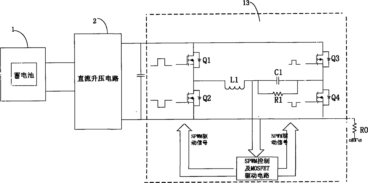
technical field The invention relates to a DC boost circuit, in particular to a DC boost circuit suitable for micro-power inverter. Background technique Photovoltaic (PV) cells generate direct current, which is stored in the battery by the controller. The battery voltage will fluctuate around 12V with the change of power. Most household appliances require AC 220V power supply, and have high requirements on the amplitude and waveform quality of AC. Traditional inverter devices generally adopt the method of inverting first and then boosting voltage, which has high cost, complicated circuit, difficult debugging and poor waveform quality. The high-frequency inverter device is a device that converts the DC power of the battery into a stable 330V DC power through a DC boost, and then converts it into a 50HZ, 220V AC power through an inverter circuit. The circuit is relatively simple, the cost is low, the digital control method is adopted, the debugging is simple, and the wavefo...
Claims
Login to View More Application Information
Patent Timeline
 Patent Type & AuthorityApplications(China)
IPC IPC(8): H02M3/337
Inventor魏学业袁磊
OwnerBEIJING JIAOTONG UNIV