Displacement sensor

A displacement sensor and shell technology, applied in the field of displacement sensors, can solve problems such as adding sensors, complex pedal structure, and car space restrictions

Inactive Publication Date: 2010-10-20
SHANGHAI VOLBOFF ELECTRON SCI & TECH
View PDF0 Cites 20 Cited by
  • Summary
  • Abstract
  • Description
  • Claims
  • Application Information

AI Technical Summary

Problems solved by technology

Therefore, the ECU of a dual kinetic energy mode vehicle needs to collect more signals than a single kinetic energy mode vehicle. However, in the prior art, if the signal output by the sensor is to be increased, the number of sensor guide rails must be increased. For this structure design, the substrate must be hard Therefore, it is necessary to increase the surface area of ​​the substrate to increase the number of sensor rails, which leads to an increase in the volume of the sensor. Another way is to increase the number of sensors and install multiple traditional position sensors on the pedal. The structure of the pedal

Method used


Image

  • Displacement sensor
  • Displacement sensor
  • Displacement sensor

Examples


Embodiment 1

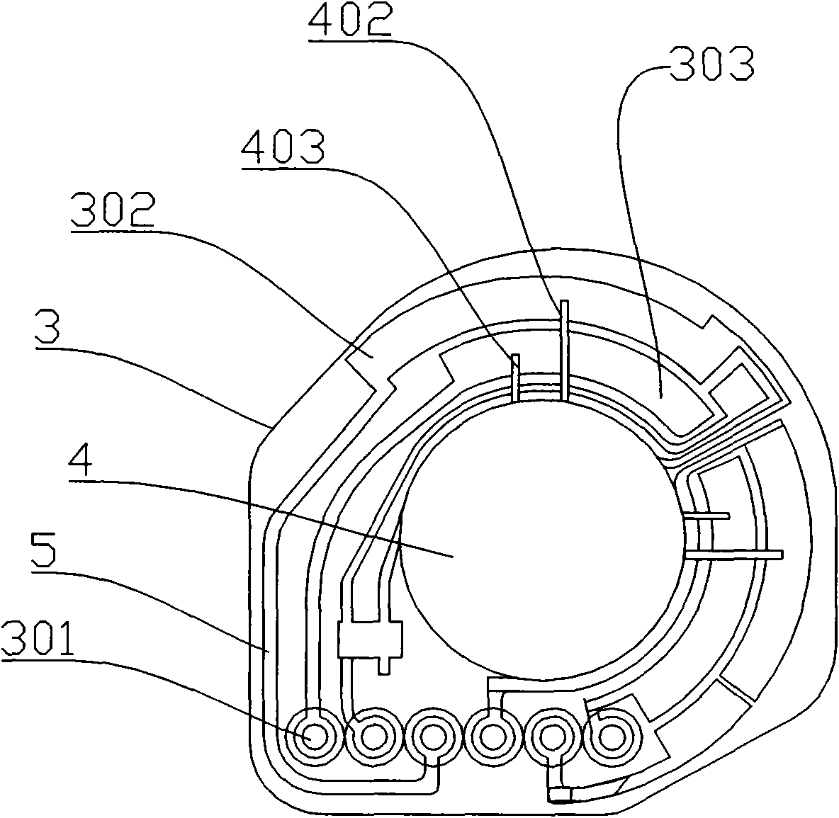
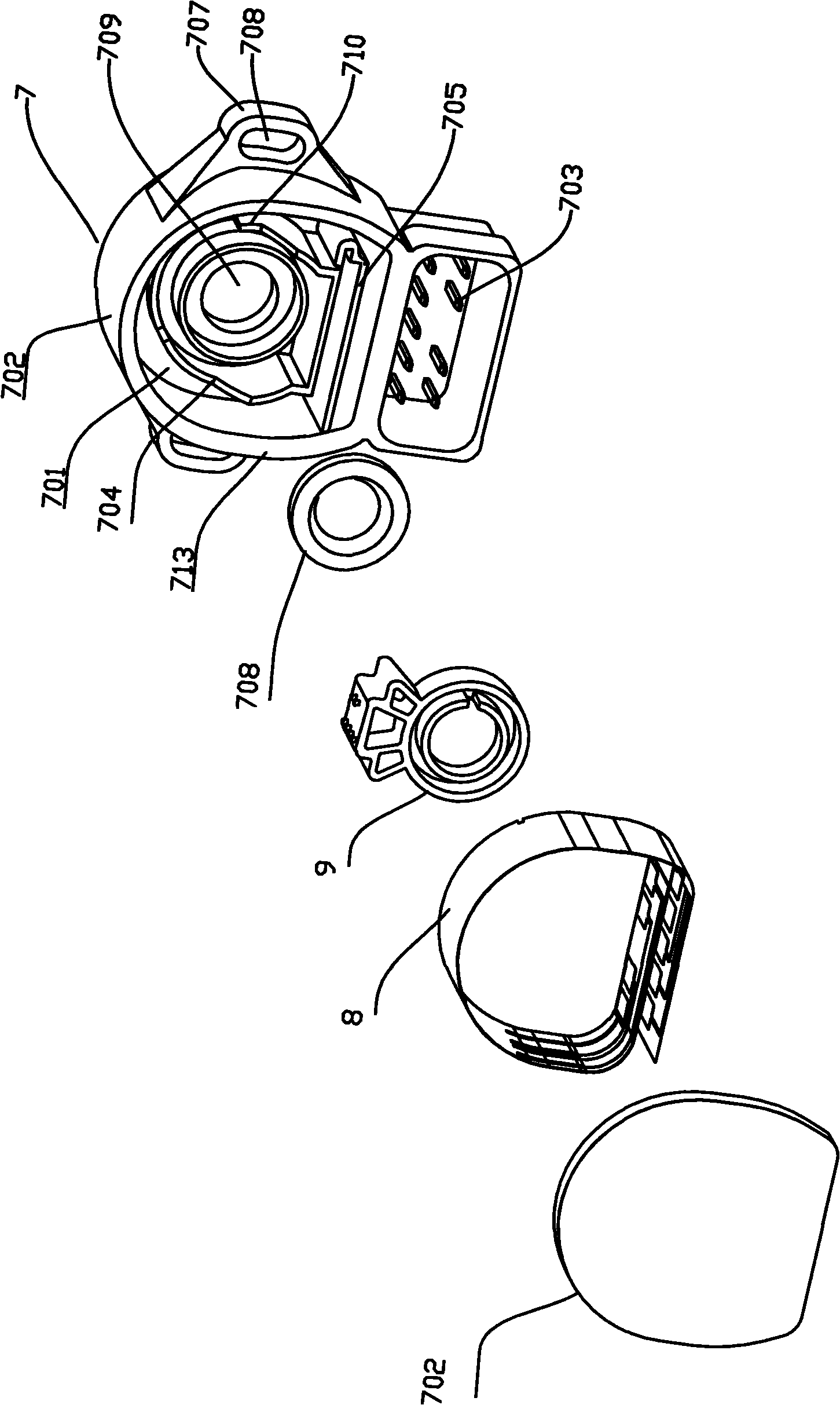
[0080] Such as image 3 , Figure 4 , Figure 5 As shown, the displacement sensor includes a housing 7, a circuit board 8, and a rotating shaft 9. The housing 7 includes a housing 713 with a cavity 701 and an end cover 706. The housing 713 has an arc portion 702, and the housing 713 is provided with 9 A metal terminal 703, one end of the metal terminal 703 can be connected to an external wire, and the other end extends to the inside of the cavity 701. Two limit baffles (704, 710) are arranged in the cavity 701, and a through hole 709 is arranged on the housing 713. To accommodate the extension of the rotating shaft 9 or the insertion of the measured object, the rotating shaft 9 is connected to the measured object to realize linkage. A cylinder 711 is arranged in the cavity 701, and the hole of the cylinder 711 is aligned with the through hole 709. The hole of the cylinder 711 The diameter of the hole is the same as that of the through hole 709. There are two parallel bracket...

Embodiment 2

[0090] It differs from Example 1 in that, as Figure 11 As shown, a notch 712 is provided on the wall of the cylinder 711; Figure 10 As shown, the rotating shaft 9 is provided with a bump 907, and the remaining parts are the same as in Embodiment 1. When installing, the bump 907 is located at the notch 712, so that the cylindrical walls at both ends of the notch 712 along the circumferential direction can limit the bump 907 radians of rotation.

[0091] In addition, the conductive rails in the circuit substrate can be arranged in 1 group, 2 groups, 4 groups or more than 4 groups.

Embodiment 3

[0093] Such as Figure 13 , 14 As shown, it is different from Embodiment 1 in that: the diameter of the hole of the cylinder 711 is the same as that of the through hole 709, the hole of the cylinder 711 is aligned with the through hole 709, a step 908 is set on the rotating shaft 9, and the waterproof ring 708 is sleeved on the rotating shaft 9, the rotating shaft 9 is inserted into the cylinder 711, and the steps 908 are mounted on the wall of the cylinder 711. All the other structures are the same as in Example 1.


PUM


Abstract

The invention discloses a displacement sensor, which is characterized in that the displacement sensor comprises a shell, a circuit board and a rotating shaft, the shell is provided with a cavity, a metal terminal is arranged on the shell, one end of the metal terminal is connected with an external conducting wire, the other end of the metal terminal extends into the cavity of the shell, and a through hole for penetrating the rotating shaft is arranged on the wall of the shell; a conductor rail is arranged on the circuit board, a resistor is arranged on the conductor rail, the resistance of the resistor changes with the length of the resistor and the conductor rail is connected with the metal terminal; a brush is arranged on the side surface of the rotating shaft and is electrically connected with the resistor; the circuit board is arranged around the rotating shaft; and the metal terminal, the conductor rail, the resistor and the brush form a resistance-adjustable conducting circuit. The volume of the displacement sensor is small but the number of lines capable of transmitting signals is large. The displacement sensor is particularly suitable for hybrid vehicles and the safety and the stability of the output signals can be ensured. Moreover, the invention has the advantages of convenient assembling, environment-friendly process, cost saving and long service life.

Description

technical field [0001] The invention relates to a displacement sensor. Background technique [0002] Faced with the gradual reduction of oil resources and the continuous introduction of environmental protection policies for automobiles by governments around the world, more and more automobile manufacturers are beginning to realize that they should increase their technology development efforts and eagerly look for new alternative energy sources. Hybrid concept cars have become the entry point for many car manufacturers. Hybrid technology is a new technology that combines the advantages of traditional engines and electric motors. It relies on the cooperation of the traditional engine and the output power of the electric motor. The charging continuously switches and converts the power generated by the motor and the engine to achieve dual kinetic energy promotion. Such cooperation is mainly driven by the electric motor and supplemented by the engine, which achieves the expected...

Claims


Application Information

Patent Timeline
IPC IPC(8): G01D5/165G01B7/30
Inventor 白宇
Owner SHANGHAI VOLBOFF ELECTRON SCI & TECH
Why Eureka
Try Eureka