Automatic fault diagnosis device of encoder and diagnosis solving method thereof

An automatic diagnosis and fault diagnosis system technology, applied in the computer field, can solve incomplete problems, achieve the effects of short time consumption, reduced human resource costs, and simple operation process

Active Publication Date: 2010-10-20
CHANGCHUN UP OPTOTECH
View PDF5 Cites 12 Cited by
  • Summary
  • Abstract
  • Description
  • Claims
  • Application Information

AI Technical Summary

Problems solved by technology

The difficulty of this type of diagnosis method is knowledge acquisition: on the one hand, it takes a long time for domain experts to accumulate the knowledge of the diagnostic object (in fact, this knowledge is always incomplete); on the other hand, it is necessary to obtain knowledge from domain experts and transform it into The production rules available to computer systems are also a big problem

Method used


Image

  • Automatic fault diagnosis device of encoder and diagnosis solving method thereof
  • Automatic fault diagnosis device of encoder and diagnosis solving method thereof
  • Automatic fault diagnosis device of encoder and diagnosis solving method thereof

Examples


Embodiment 1

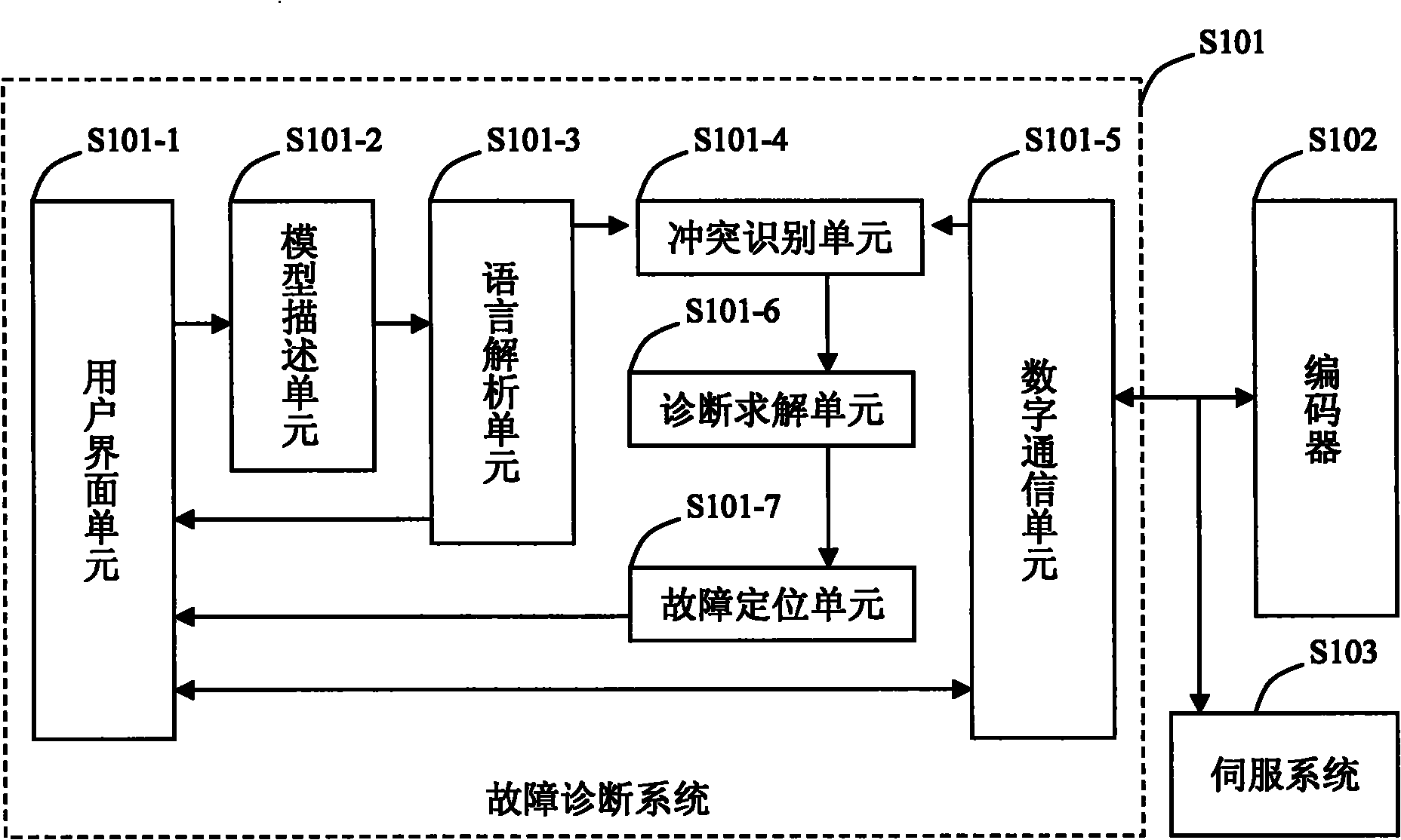
[0033] The first preferred embodiment of the present invention illustrates the implementation and application of the method of the present invention through fault diagnosis of a certain type of encoder. The fault diagnosis system applying the present invention communicates with the encoder under test through a serial port. The system sends out a command frame, accepts the corresponding state data and output of the encoder under test, and compares it with the expected result. In other embodiments, it may also be connected to the encoder under test through an interface such as a network cable or a USB cable.

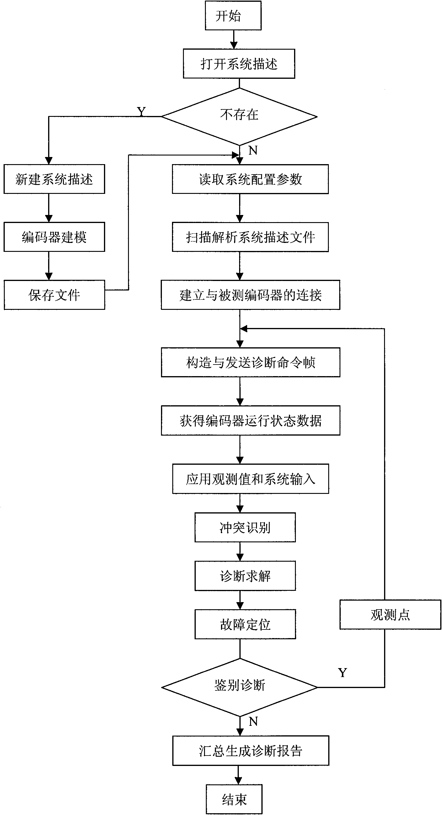
[0034] image 3 The flow process of implementing the fault diagnosis method of the present invention is provided, specifically including:

[0035] 1) After the fault diagnosis system is started, the user opens a system description file using the specified location in the dialog box;

[0036] 2) If there is no legal system description at this location, create a new system...

Embodiment 2

[0051] The second preferred embodiment of the present invention illustrates the implementation and application of this fault diagnosis method through a diagnostic test of a certain 24-bit absolute encoder. Various electromagnetic interference sources and mechanical vibrations on the production site interfere with the photoelectric detection of the encoder, resulting in distortion of the output waveform, resulting in instability or malfunction of the control system, and even accidents. For example; in the steel rolling speed control system, the encoder is directly fixed on the shell of the motor. When the rolling mill passes through the steel, it will cause the vibration of the motor shaft and the casing, which will cause the encoder to malfunction and cause an accident. The method of the invention is used to carry out diagnosis test and process control on the encoder, so as to improve the reliability of the whole machine system.

[0052] Assuming that this embodiment has a co...


PUM


Abstract

The invention belongs to the technical field of computers, relating to fault diagnosis system and method of an encoder based on logic compatibility and aiming to provide an automatic fault diagnosis device of an encoder and a diagnosis solving method thereof. The fault diagnosis system comprises a user interface unit, a model description unit, a language analysis unit, a conflict recognition unit, a diagnosis solving unit, a fault positioning unit and a digital communication unit. The system is specially characterized in that the structure, function and component behavior of the encoder is prescriptively described by using a model description language according to an encoder constitution principle, accordingly, the expected behavior of the encoder under normal circumstances is deduced, differences exist between the expected behavior and an actual observation when a fault occurs, and then a component set triggering the fault is confirmed by using logical deduction. In the invention, from the conflict recognition to the generation of candidate diagnosis, the whole operation process is simple and needs short time, and the discrimination and positioning of the system on a fault point does not depend on the experience of an operator or an expert, thereby the limitations of the traditional diagnosis method are overcome.

Description

technical field [0001] The invention belongs to the field of computer technology, and relates to an encoder fault diagnosis system and method based on logic compatibility, in particular to an automatic encoder fault diagnosis device and a diagnosis solution method thereof. technical background [0002] An encoder is a device that compiles and converts physical signals or data into forms that can be used for communication, transmission and storage. It is an important sensing product for speed measurement and positioning purposes. Encoders are an important branch of sensing products and have a very broad market, such as machine tools, aerospace, railway transportation, new energy and port machinery, etc., are using a large number of encoder products. [0003] The encoder converts the collected physical quantity (angular displacement or linear displacement) into an electrical signal that can be read by machine code through the binary code of "1" and "0", which is used for commu...

Claims


Application Information

Patent Timeline
Patent Type & Authority Applications(China)
IPC IPC(8): G01D18/00
Inventor 陈荣陈达文李俊义吴志勇徐俊杰曹永刚陈能曹晶
Owner CHANGCHUN UP OPTOTECH
Why Eureka
Try Eureka