
Torsional vibration excitation device and test bed of vehicle drive system

A vibration excitation device and transmission system technology, which is applied in the field of vehicle transmission system test equipment, can solve problems such as complex structure, high cost, and limitation of excitation frequency, and achieve the effects of strong anti-interference, large adjustment amount, and precise control

Inactive Publication Date: 2010-10-20
CHONGQING UNIV
View PDF7 Cites 57 Cited by
  • Summary
  • Abstract
  • Description
  • Claims
  • Application Information

AI Technical Summary

Problems solved by technology

But its disadvantages are: the output characteristics of the simulation are not the sinusoidal excitation that is usually used to analyze the torsional vibration characteristics, and the torsional resonance response test of the entire transmission system cannot be carried out; at the same time, this test bench also has the defects of complex structure and high cost
But its disadvantage is: when the drive shaft rotates at a certain speed, the excitation frequency can only be twice the speed of the drive shaft, and when the drive shaft rotates at a certain speed, the excitation frequency is also limited
[0008] In addition, the above-mentioned virtual engine simulator and vehicle transmission system dynamic simulation test bench both simplify the wheel into a wheel inertia disk, and the equivalent inertia disk of the whole vehicle is directly connected to the wheel inertia disk through a rigid shaft, so the tire characteristics cannot be studied Influence on the torsional vibration characteristics of the transmission system

Method used


Image

  • Torsional vibration excitation device and test bed of vehicle drive system
  • Torsional vibration excitation device and test bed of vehicle drive system
  • Torsional vibration excitation device and test bed of vehicle drive system

Examples


Embodiment Construction

[0031] The present invention will be described below in conjunction with the accompanying drawings.

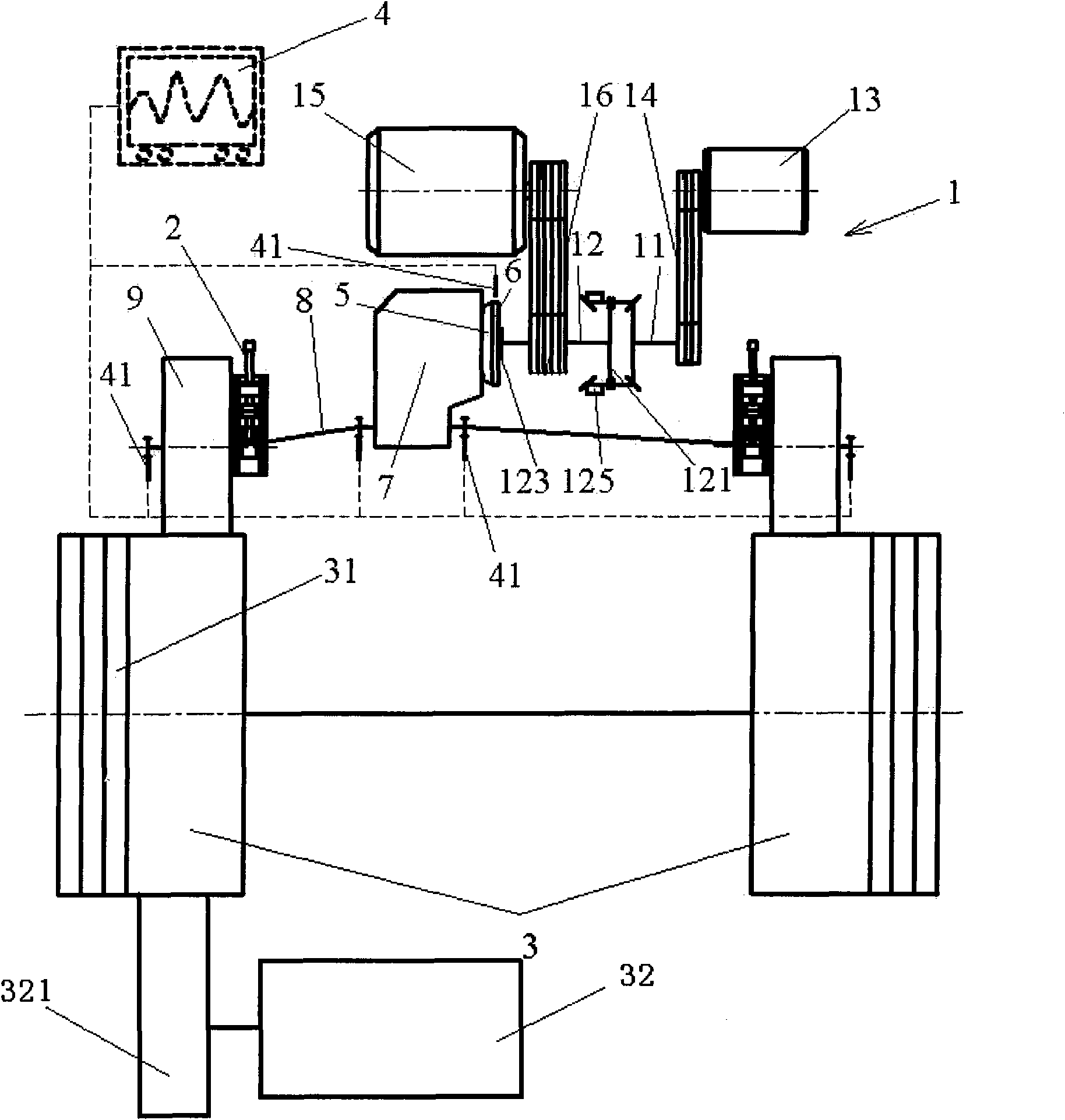
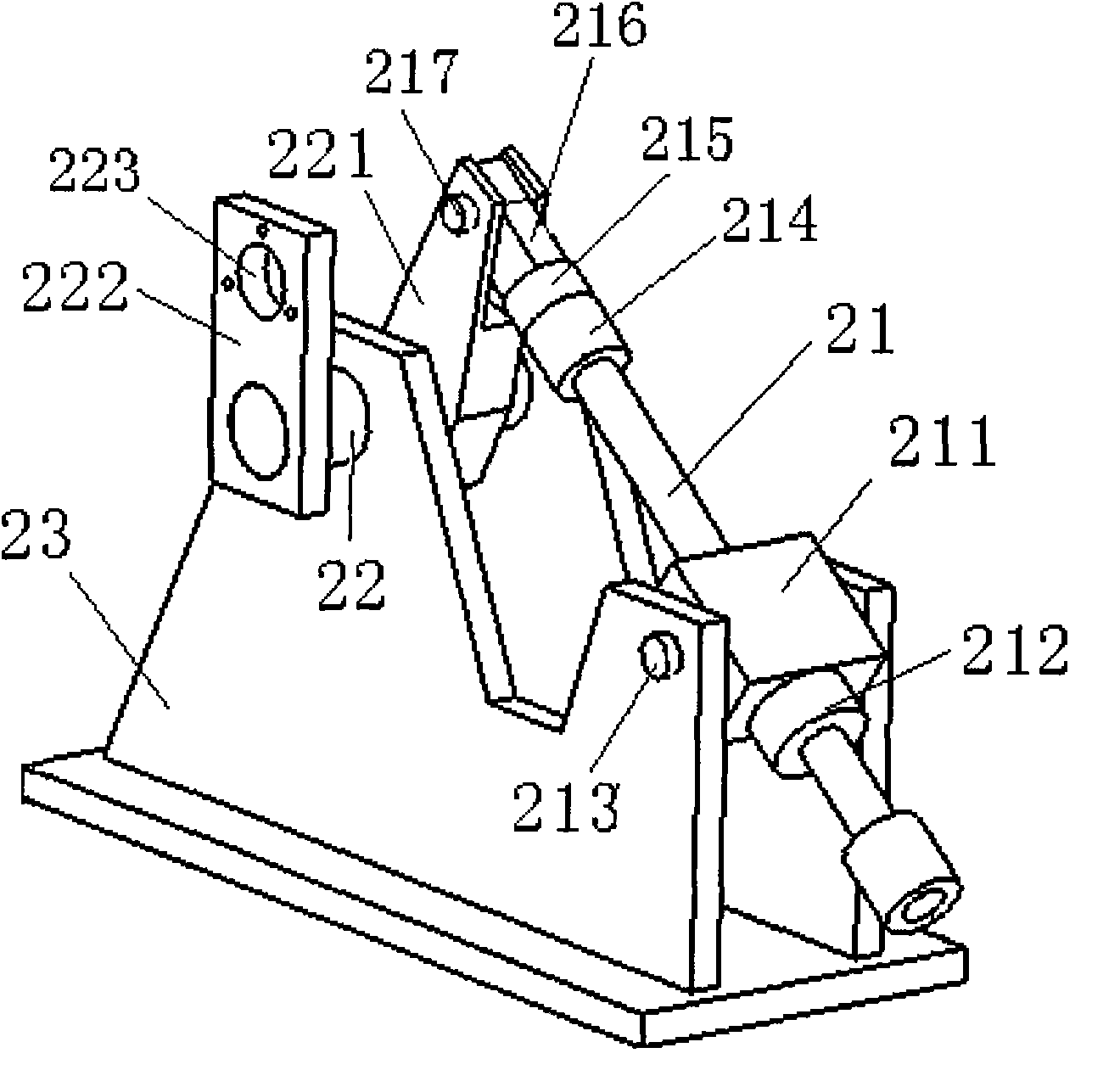
[0032] Such as figure 1 As shown, the test bench of the present invention includes a torsional vibration excitation device 1 , a wheel loading device 2 , an inertia flywheel 3 and a test system 4 . Wherein the torsional vibration excitation device 1 is connected with the flywheel 6 of the transmission system, and the flywheel 6 is connected with the clutch 5 and the transmission differential 7 in turn; the transmission and the differential 7 of the vehicle transmission system are connected with the wheels 9 through the half shaft 8; the wheels 9 It is installed on the loading device 2, and the wheel 9 is pressed against the inertia flywheel 3 by the loading device 2, so that the inertia flywheel 3 is driven by the wheel 9 through friction. The torsional vibration excitation device 1 is used to provide torsional vibration excitation torque with adjustable amplitude and frequen...


PUM


Abstract

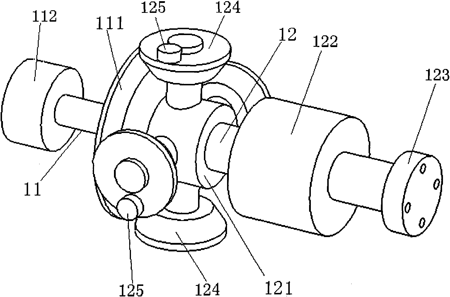
The invention relates to a torsional vibration excitation device and a test bed of a vehicle drive system, comprising a torsional vibration excitation device, a wheel loading device, an inertia flywheel and a testing system. The torsional vibration excitation device is used for providing a torsional vibration excitation torque for the torsional vibration research of the drive system and providing power for the drive system. The wheel loading device is used for supporting wheels and simulating a carload acting on the wheels, pressing the wheels towards the inertia flywheel through a mechanical loading mode and locking the positions of the wheels. The testing system is used for collecting pull and pressure signals as well as rotate speed signals output by a sensor and analyzing the pull and pressure signals as well as the rotate speed signals. The torsional vibration excitation device comprises a driving motor, a driving gear shaft, an excitation gear shaft and an excitation motor, wherein the driving motor drives the driving gear shaft to rotate through the belt of the driving motor, the excitation motor drives the excitation gear shaft to rotate through the belt of the excitation motor, and the excitation gear shaft is coaxial with the driving gear shaft.

Description

technical field [0001] The invention relates to a vehicle transmission system test device, in particular to a vehicle transmission system torsional vibration excitation device and a test bench. Background technique [0002] The vehicle transmission system is the main moving component of the car, which is used to provide and transmit the driving power of the car, generally including the engine, clutch, transmission, final reducer, differential and drive half shaft, etc. For front and rear drive cars, it also includes Longer drive shaft. The vehicle transmission system is a multi-degree-of-freedom torsional resonance system. Due to the rough and unstable operation of the engine and the fluctuation of the driving load, the periodic torsional excitation frequency will be generated. When the torsional excitation frequency is consistent with the natural frequency of the torsional vibration of the transmission system, it will be Torsional resonance (hereinafter referred to as tors...

Claims


Application Information

Patent Timeline
Patent Type & Authority Applications(China)
IPC IPC(8): G01M17/007G01M13/02G01M7/02
Inventor 邓兆祥姜艳军袁晨恒李进超杨维军
Owner CHONGQING UNIV
Learn More