Spherical thin-film solar cell, preparation method thereof and spatial arrangement assembly based on cell

A technology of thin-film solar cells and thin-film batteries, which can be applied to circuits, photovoltaic power generation, electrical components, etc., and can solve problems such as inability to absorb sunlight to the maximum

Inactive Publication Date: 2012-03-28
CHANGZHOU UNIV
View PDF0 Cites 0 Cited by
  • Summary
  • Abstract
  • Description
  • Claims
  • Application Information

AI Technical Summary

Problems solved by technology

[0003] Most of the traditional solar cells are planar, that is, receive light on one side, and cannot absorb sunlight to the maximum under all-day light conditions, and the components are also arranged in a plane

Method used


Image

  • Spherical thin-film solar cell, preparation method thereof and spatial arrangement assembly based on cell
  • Spherical thin-film solar cell, preparation method thereof and spatial arrangement assembly based on cell
  • Spherical thin-film solar cell, preparation method thereof and spatial arrangement assembly based on cell

Examples


Embodiment 1

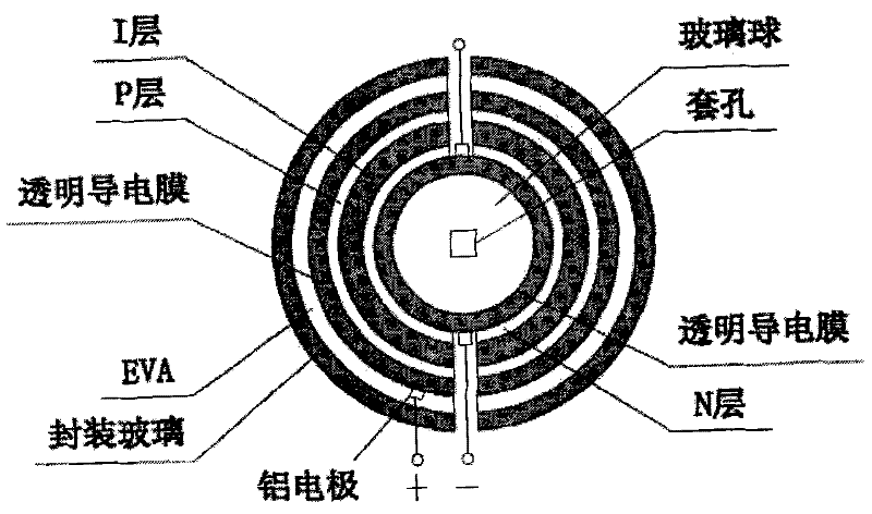
[0044] 1. Structural design of solar cells

[0045] The diameter of the glass sphere is 10cm, and a 50nm-thick ITO film is sequentially grown on the glass sphere, hydrogenated nano-silicon NIP structure (N, I, P layer thicknesses are 10, 400, 10nm, respectively), and a 70nm-thick Al x Zn 1-x O(x=0.02) thin film, lead out aluminum electrodes, and finally use EVA and two hemispherical glass for encapsulation. (Such as figure 1 shown)

[0046] 2. Preparation of solar cells

[0047] 2.1 Cleaning of glass balls

[0048] The glass spheres were ultrasonically cleaned with acetone, rinsed with deionized water, and dried.

[0049] 2.2 Preparation of transparent bottom electrode by sputtering method

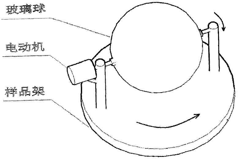
[0050] The background vacuum of the sputtering chamber is 1×10 -4 Pa, use the sputtering method to sputter the ITO ceramic target on the cleaned glass ball, and deposit the ITO film with a thickness of about 50nm. Glass spheres are mounted on a three-dimensional sample stage (such ...

Embodiment 2

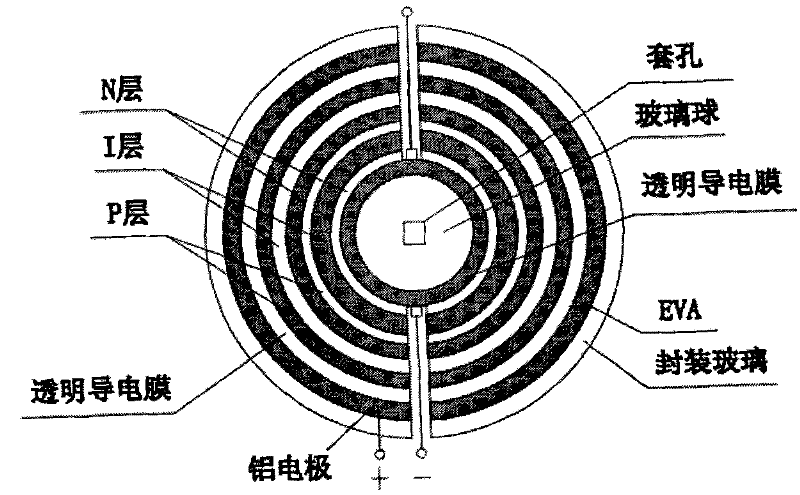
[0066] Structural Design of Solar Cells

[0067] The diameter of the glass sphere is 10cm, and the ITO film with a thickness of 50nm is grown successively on the glass sphere, and the amorphous silicon / microcrystalline silicon laminated battery (the N, I, and P layer thicknesses of the microcrystalline silicon bottom battery are 10, 1000, 10nm respectively, The thickness of the N, I, and P layers of the amorphous silicon top cell is 10, 200, and 10nm respectively), and the 70nm thick Al x Zn 1-x O(x=0.02) thin film, lead out aluminum electrodes, and finally use EVA and two hemispherical glass for encapsulation. (Such as figure 2 )

[0068] The difference from Embodiment 1 is that the thin film battery adopts the laminated structure of amorphous silicon / microcrystalline silicon film and uses the PECVD method to prepare hydrogenated amorphous silicon / microcrystalline silicon laminated battery on the bottom electrode.

[0069] Glass spheres are mounted on a three-dimensional...


PUM


Abstract

The invention relates a spherical thin-film solar cell structure, a preparation method thereof and a spatial arrangement mode of assembly composing the cell unit, belonging to the manufacturing field of the solar cell. Both a bottom electrode and an upper electrode of the spherical cell use transparent conducting films. By using the spherical structure, on one hand, sunlight in all directions canbe absorbed, thereby avoiding using a sunlight tracker; and on the other hand, light rays are refracted and reflected for many times in the small spherical body to form a good light trapping structure, thereby greatly improving the light absorption efficiency. The structure of the spherical cell assembly can enable the cells to be spatially accumulated, thereby improving the space utilization ratio to obtain a larger light receiving area. In order to ensuring the uniformity of thin film deposition, a three-dimensional rotating sample platform is used. The spherical thin-film cells are arranged in the space according to a Fibonacci spiral phyllotaxis to form the solar cell assembly. Compared with the tiled arrangement of the cells, the spatial arrangement mode can manyfold increase the light-receiving area of the cells under the condition of equal occupying area.

Description

technical field [0001] The invention relates to a thin-film solar cell with a spherical structure, a method for preparing the solar cell with the structure, and a cell assembly based on the spatial arrangement of the spherical solar cell units, belonging to the field of solar cell manufacturing. Background technique [0002] With the increasingly serious energy crisis and environmental pollution, the development of renewable clean energy has become one of the major strategic issues in the international scope. Solar energy is an inexhaustible clean energy source, therefore, the development and utilization of solar energy has become a strategic decision for sustainable energy development in countries all over the world. [0003] Most of the traditional solar cells are planar, that is, receive light on one side, and cannot absorb sunlight to the maximum under all-day light conditions, and the components are also arranged in a plane. On the one hand, the spherical structure of ...

Claims


Application Information

Patent Timeline
Patent Type & Authority Patents(China)
IPC IPC(8): H01L31/042H01L31/20
CPCY02E10/50Y02P70/50
Inventor 丁建宁袁宁一王书博叶枫陈明明
Owner CHANGZHOU UNIV
Why Eureka
Try Eureka