Millimeter-wave image analysis method, fire monitoring method and system

An image analysis, millimeter wave technology, applied in image enhancement, fire alarm, image data processing, etc., can solve problems such as loss, and achieve the effect of large protection range and wide monitoring range

Inactive Publication Date: 2010-10-20
刘文萍
View PDF6 Cites 20 Cited by
  • Summary
  • Abstract
  • Description
  • Claims
  • Application Information

AI Technical Summary

Problems solved by technology

[0007] The purpose of the present invention is to solve the technical problem that the existing fire alarm detection system uses the infrared image of the flame to identify the fire, and the alarm information is generated after the fire occurs, causing unnecessary losses

Method used


Image

  • Millimeter-wave image analysis method, fire monitoring method and system
  • Millimeter-wave image analysis method, fire monitoring method and system
  • Millimeter-wave image analysis method, fire monitoring method and system

Examples


Embodiment 1

[0041] The first embodiment is a case where the fire monitoring system is applied to a small-scale monitoring area.

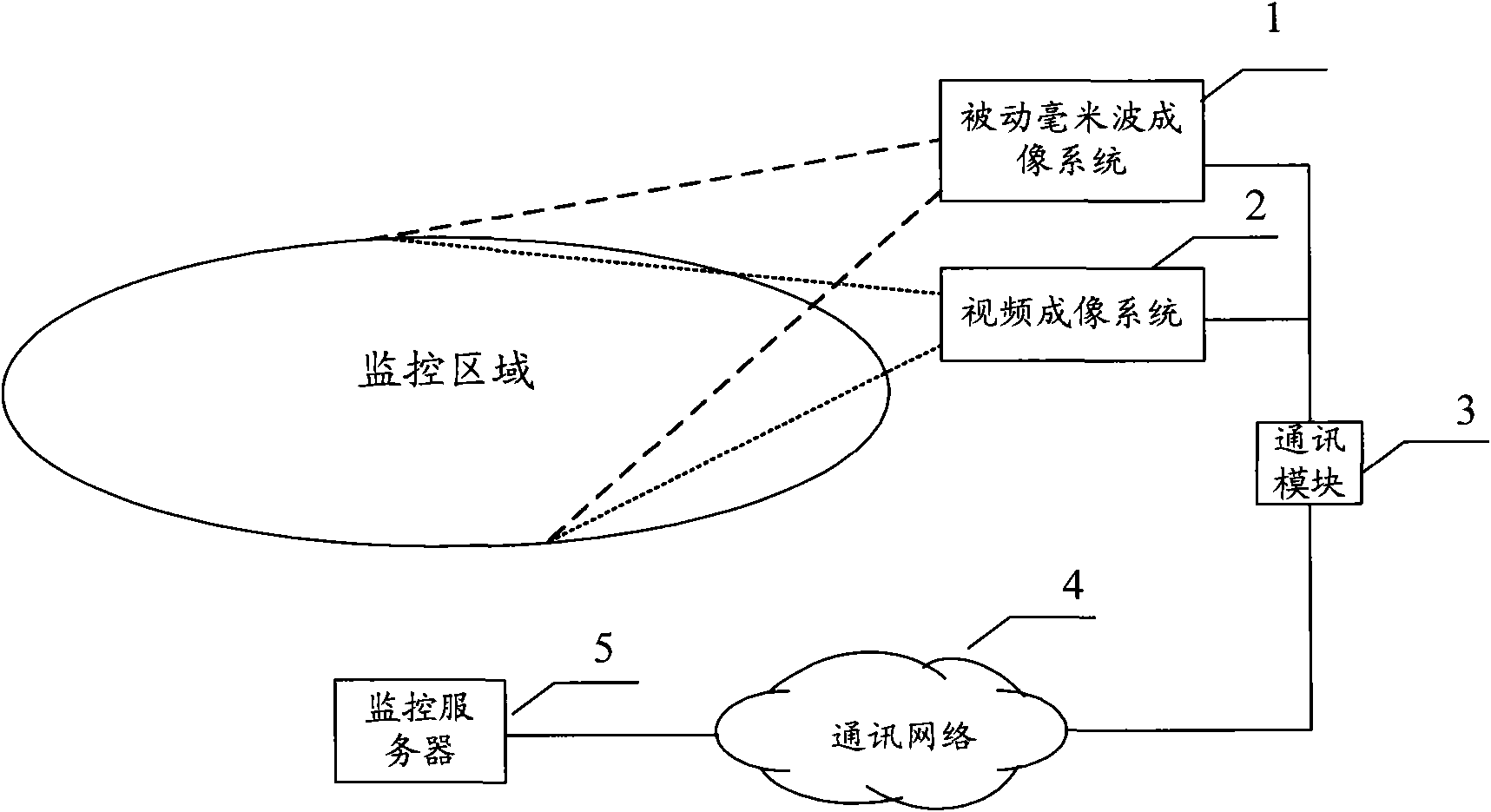
[0042] The fire monitoring system of the first embodiment is composed of a passive millimeter wave imaging system 1, a video imaging system 2, a communication module 3, a communication network 4 and a monitoring server 5.

[0043] The passive millimeter wave imaging system 1 and the video imaging system 2 are set in the monitoring area, and are connected to the monitoring server 5 through the communication module 3 and the communication network 4.

[0044] The passive millimeter wave imaging system 1 detects and receives electromagnetic radiation in the monitored area, converts the received signal into a millimeter wave image, recognizes the millimeter wave image, and judges whether there is a suspicious fire area. When the judgment result is that there is a suspicious fire area, the passive millimeter wave imaging system 1 sends an alarm message to the monitoring ser...

Embodiment 2

[0075] Image 6 Shown is a schematic diagram of the fire monitoring system of the second embodiment.

[0076] The fire monitoring system of the second embodiment is applied to a monitoring area with a large range. The passive millimeter wave imaging system is fixedly installed around the monitoring area, and the number of installations required is determined according to the detection range of each passive millimeter wave imaging system, so that all The passive millimeter wave imaging system can effectively protect the entire monitoring area.

[0077] The fire monitoring system of the second embodiment is composed of a plurality of passive millimeter wave imaging systems 1, a plurality of video imaging systems 2, a communication module 3, a communication network 4 and a monitoring server 5.

[0078] The passive millimeter wave imaging system 1 and the video imaging system 2 are set in a monitoring area in pairs, and are connected to the monitoring server 5 through the communication m...

Embodiment 3

[0103] Picture 9 Shown is a schematic diagram of the fire monitoring system of the third embodiment.

[0104] The fire monitoring system of the third embodiment is applied to a large monitoring area. The passive millimeter wave imaging system is installed on a rotatable pan / tilt, and the pan / tilt is fixed in the center of the monitoring area. The passive millimeter wave imaging system can be accompanied by the pan / tilt. Rotate.

[0105] The fire monitoring system of the third embodiment is composed of a passive millimeter wave imaging system 1, a video imaging system 2, a communication module 3, a communication network 4 and a monitoring server 5, as well as a driving device 6 and a pan-tilt 7.

[0106] The passive millimeter wave imaging system 1 and the video imaging system 2 are paired on the pan-tilt 7 and connected to the monitoring server 5 through the communication module 3 and the communication network 4. The passive millimeter wave imaging system 1 and the video imaging sy...


PUM


Abstract

The invention provides a millimeter-wave image analysis method, which comprises the following steps: acquiring a millimeter-wave image of a monitored region; carrying out image segmentation on the millimeter-wave image and obtaining a binary image; carrying out region filling on the binary image; carrying out connected region labeling on the binary image after the region filling, and obtaining the maximum connected region which is a suspicious fire region; and carrying out fire point judgment on the suspicious fire region, and judging whether the suspicious fire region is the region which is bound to cause fire or not. The invention provides a fire monitoring system which comprises at least one passive millimeter-wave imaging system, at least one video imaging system, a communication module, a communication network and a monitoring server, wherein the millimeter-wave imaging system is used for acquiring the millimeter-wave image of the monitored region, analyzing the millimeter-wave image, judging the region which is bound to cause the fire, producing alarm information and sending the alarm information to the monitoring server; and the video imaging system is arranged in the monitored region and used for acquiring a video image of the monitored region.

Description

Technical field [0001] The invention relates to a monitoring system and method, in particular to a fire early warning and monitoring technology based on millimeter wave image recognition and processing. Background technique [0002] Fire is a disaster caused by uncontrolled combustion. Three conditions must be prepared for the occurrence and development of the combustion process: combustibles, oxidizers and temperature. If you want to prevent fire, you only need to destroy any one of the three basic conditions of combustion. Under normal circumstances, both combustibles (trees) and oxides (air) are available in the forest environment and are not easy to control. However, temperature can be detected and controlled under normal circumstances. [0003] To minimize the losses caused by fire, the most critical issue in fire science is fire detection and location technology. [0004] The temperature and time curve of the object itself when the object is burning is like figure 1 As shown...

Claims


Application Information

Patent Timeline
Patent Type & Authority Applications(China)
IPC IPC(8): H04N7/18G06T5/00G08B17/00G08B25/01
Inventor 刘文萍
Owner 刘文萍
Why Eureka
Try Eureka