
Line heat source

A wire heat source and a wire-line technology, applied in the field of wire heat sources based on carbon nanotubes, can solve the problems of being easily damaged, the quality of the heating wire is large, unfavorable to the micro heat source, etc., and achieve the effects of not being easily damaged, and having high mechanical strength and toughness.

Active Publication Date: 2013-07-03
TSINGHUA UNIV +1
View PDF7 Cites 0 Cited by
  • Summary
  • Abstract
  • Description
  • Claims
  • Application Information

AI Technical Summary

Problems solved by technology

[0004] However, the heating wire made of metal, alloy or carbon fiber has the following disadvantages: first, the heat generated by the heating wire radiates outwards at ordinary wavelengths, and its electrothermal conversion efficiency is not high, which is not conducive to saving energy. Cotton thread coated with far-infrared paint to improve electrothermal conversion efficiency
Second, the size of carbon fiber is not small enough, which is not conducive to the application of micro heat sources. When the diameter of the metal wire is small, the strength is very low and easy to break, which is not conducive to the application of micro heat sources.
Third, the mass of the heating wire is relatively large, which is not conducive to the lightening of the heat source
However, the carbon nanotube filaments in this patent document are used for luminescence. Since the mechanical strength and toughness of the directly obtained pure carbon nanotube filaments are not good enough, they are easily destroyed during use, thus limiting the use of carbon nanotube filaments. Use range, can not be used directly for heat source

Method used


Image

  • Line heat source
  • Line heat source
  • Line heat source

Examples


preparation example Construction

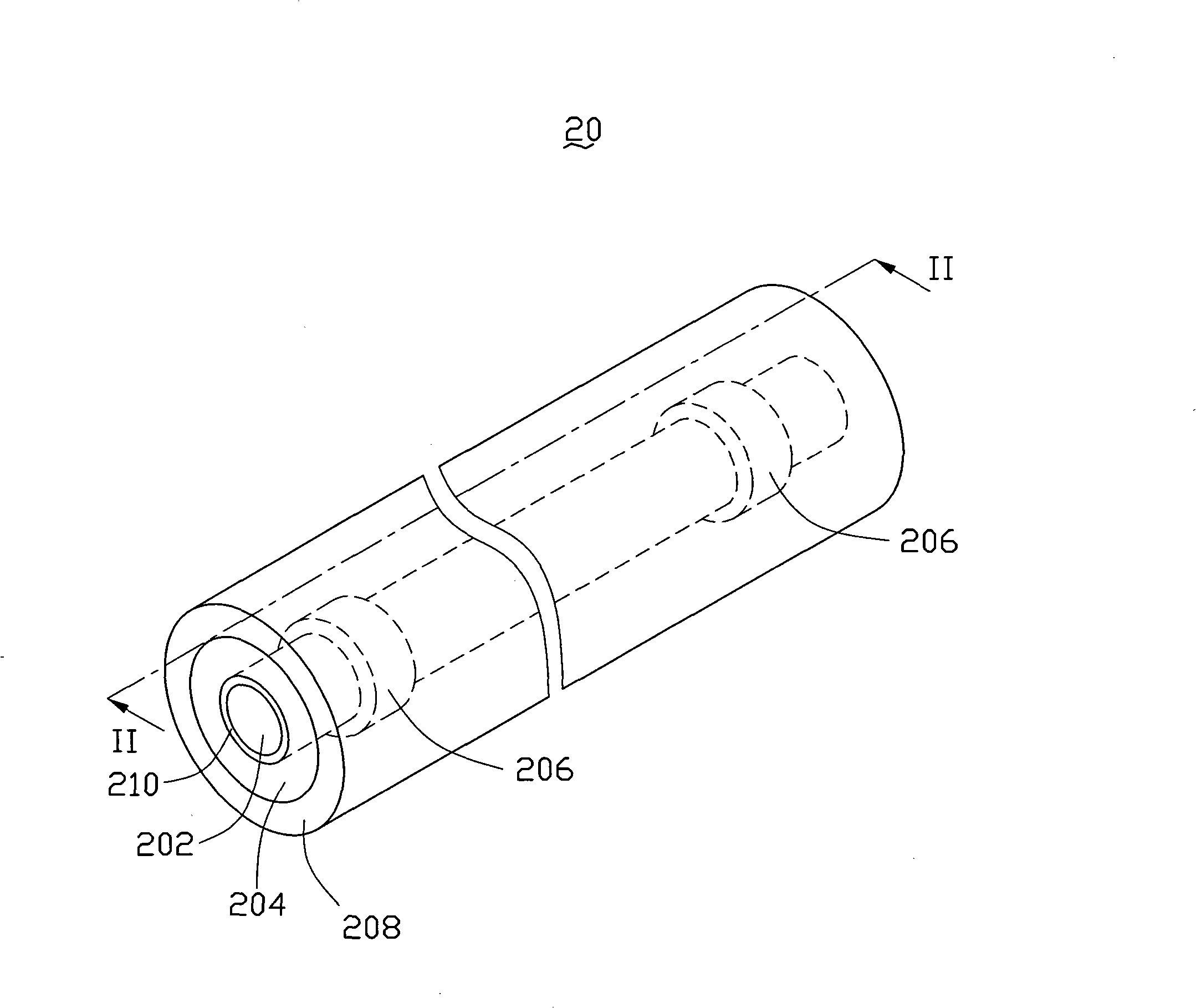
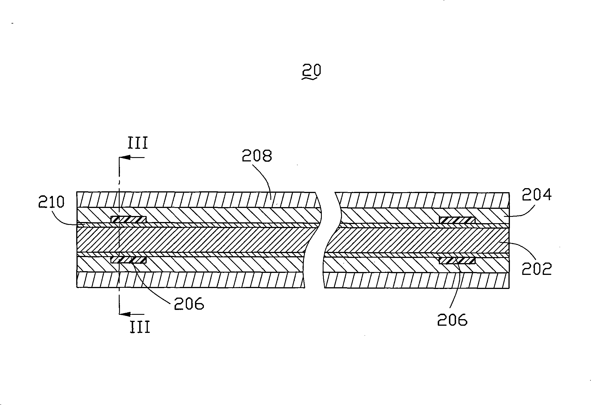
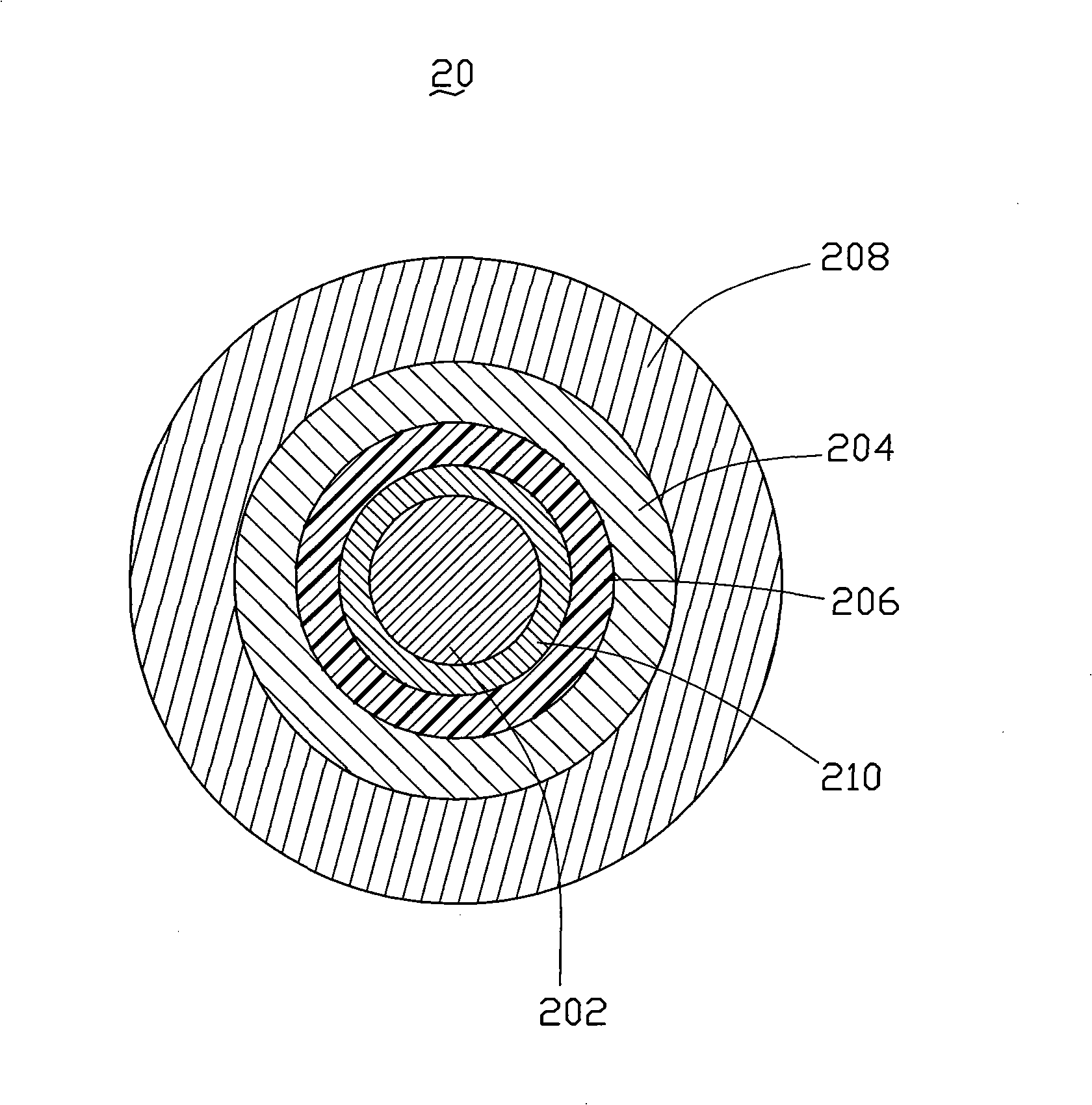
[0071] See Figure 16 , The first embodiment of the present invention further provides a method for preparing the linear heat source 20, which specifically includes the following steps:

[0072] Step S101, providing a carbon nanotube structure.

[0073] According to the difference of the carbon nanotube structure, the preparation method of the carbon nanotube structure includes: direct film drawing method, rolling method, flocculation method and the like. The preparation methods of the above-mentioned carbon nanotube structures will be separately described below.

[0074] (1) When the carbon nanotube structure includes at least one drawn carbon nanotube film, the method for preparing the carbon nanotube structure includes the following steps:

[0075] First, a carbon nanotube array is provided on a growth substrate, and the array is preferably a super-in-line carbon nanotube array.

[0076] The preparation method of the carbon nanotube array adopts the chemical vapor deposition method,...


PUM

PropertyMeasurementUnit
diameteraaaaaaaaaa
thicknessaaaaaaaaaa
thicknessaaaaaaaaaa

Abstract

The invention relates to a line heat source comprising a heating element and two electrodes, wherein the two electrodes are arranged at intervals and are electrically connected with the heating element; and the heating element comprises at least one line-shaped carbon nano pipe composite structure, wherein the line-shaped carbon nano pipe composite structure comprises a basal body and at least one carbon nano pipe line-shaped structure compounded in the basal body. The line heat source can be used for manufacturing heating clothes, heating gloves or heating shoes with spontaneous heating, an electric heater, an infrared therapeutic apparatus, an electric room heater and the like and has extensive application range.

Description

Technical field [0001] The invention relates to a linear heat source, in particular to a linear heat source based on carbon nanotubes. Background technique [0002] Heat sources play an important role in people's production, life, and scientific research. The linear heat source is a kind of heat source, which has a wide range of applications in industrial fields, scientific research fields or life fields, such as electric heating tubes, electric blankets, infrared therapy instruments and electric heaters. [0003] The existing linear heat source usually includes a linear heating element (such as a resistance wire, etc.) and two electrodes. The two electrodes are spaced apart and electrically connected to both ends of the linear heating element. When a voltage or current is applied to the linear heating element through the two electrodes, the linear heating element generates Joule heat, and the heat is radiated outward at a common wavelength. Generally, the linear heating element ...

Claims


Application Information

Patent Timeline
Patent Type & Authority Patents(China)
IPC IPC(8): B82B1/00H05B3/40H05B3/14
CPCH05B2214/04
Inventor 刘锴冯辰姜开利王佳平范守善
Owner TSINGHUA UNIV
Learn More