Furniture arch beam arm structure and preparation method thereof

A manufacturing method and technology of furniture curvature, which can be applied to home appliances, furniture parts, and other seating furniture, etc., and can solve problems such as difficulty in improving production efficiency, difficulty in mass production, and different extension curvatures.

Inactive Publication Date: 2010-10-27
NEW CHANNEL
View PDF2 Cites 9 Cited by
  • Summary
  • Abstract
  • Description
  • Claims
  • Application Information

AI Technical Summary

Problems solved by technology

In the above structure, since the shape of the two side brackets 50 combined with the back beam arm 7 is similar to the shape of the lower bracket 60 (and the seat 601), and in order to conform to ergonomics, the two side brackets 50 and the back beam arm 7 The combined shape is larger than the lower bracket 60 (and the seat 601), so that the backboard 73 and the side partition 501 are arranged in an oblique direction gradually expanding upwards. According to the requirement of performance, the backrest plate 73 should be connected upwards to the bottom edge of the backrest beam arm 7 on the side of the seat 601. Therefore, the structure of the backrest beam arm 7 should be as follows: figure 2 As shown, the joint surface 71 with the same cross-sectional shape as the side bracket 50 is provided on the edge of its two ends to form a smooth joint with the side bracket 50, while the middle section 72 of the back beam arm 7 is provided with a joint on the inner edge. The backboard 73 has an upward inclined arc surface 721, therefore, the middle section 72 basically has a trapezoidal section with a large bottom and a small top (and the shape of the trapezoidal section can make the opposite side of the hypotenuse also have an appropriate angle of inclination ), and the connecting surface 71 between the middle section 72 and the two sides has different curvatures and cross-sectional shapes. For wood raw materials of this shape, the processing is mostly to bake

Method used


Image

  • Furniture arch beam arm structure and preparation method thereof
  • Furniture arch beam arm structure and preparation method thereof
  • Furniture arch beam arm structure and preparation method thereof

Examples


Embodiment Construction

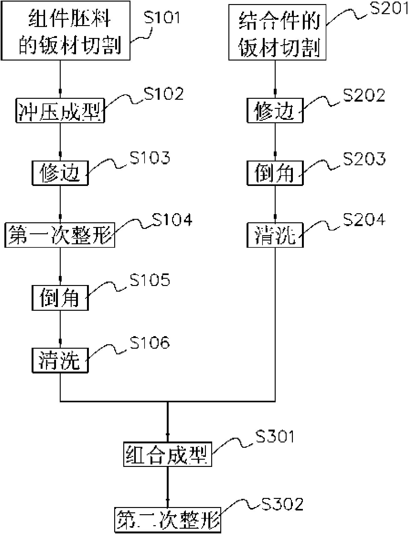
[0046] See image 3As shown, it can be seen that the manufacturing method of the present invention mainly includes: "sheet material cutting of component blanks" S101, "stamping" S102, "trimming" S103, "first shaping" S104, "chamfering" S105, " Cleaning" S106, "Sheet cutting of combined parts" S201, "Trimming" S202, "Chamfering" S203, "Cleaning" S204, "Combined forming" S301, "Second shaping" S302 and other steps, in which the " Sheet material cutting of component blanks" S101 step is to cut metal sheet materials by ionization (laser) or other methods to form at least one basic sheet shape required by component blanks; after a "stamping" step S102 Process the sheet metal of the above-mentioned component blanks with punching machines, presses and other tools to form a semi-finished component with a ㄇ-shaped cross-section that meets the required curvature and shape; and then use a milling machine (or CNC processing machine) to remove the excess edge material of the semi-finished...


PUM


Abstract

The invention relates to a furniture arch beam arm structure and a preparation method thereof. The preparation method mainly adopts the stamping mode to ensure metal plates are used to separately form different components and connectors; the components and connectors adapt to the curvatures and shapes of different parts of a preset beam arm, wherein each component contains an opening of which width is expanded slantways to one side, the connectors are connected at the openings to form a plurality of sealed hollow tubular scaffolds; and the scaffolds are connected mutually and dressed properly to form a beam arm structure with the preset and complete curvature and shape which is used to connected with other furniture component. The tubular structure formed by metal material is used to replace the original wooden beam arm structure, thus reducing the material cost, simplifying the processing procedure of the arch beam arm structure in the furniture and increasing the overall production efficiency.

Description

Technical field: [0001] The invention relates to a furniture curved bow arm structure and a manufacturing method thereof, in particular to a tubular beam arm structure suitable for different curvatures and cross-sectional shape changes and a processing method thereof. Background technique: [0002] Because wood is easy to process and its material characteristics (such as surface texture and fragrance), it has been widely used in general or high-end furniture since ancient times. However, due to the high level of wood processing technology and the difficulty of mass production, the production cost cannot be effective. The decline is not in line with economic benefits, coupled with the rapid disappearance of forest resources, and the rise of people's awareness of environmental protection, it is becoming more and more difficult to obtain various wood raw materials. This is also a trend that is difficult to overcome. Metal) to replace wood as the main material of furniture is th...

Claims


Application Information

Patent Timeline
IPC IPC(8): A47C7/00A47C5/04A47B96/00B23P15/00
Inventor 张家玮
Owner NEW CHANNEL
Why Eureka
Try Eureka