
Double-workbench drive laser processing machine and processing method thereof

A laser processing machine and dual-table technology, applied in laser welding equipment, metal processing equipment, manufacturing tools, etc., can solve the problems of low processing efficiency, poor automatic visual alignment accuracy, and insufficient flexibility of mechanical punching machines.

Inactive Publication Date: 2010-10-27
THE 45TH RES INST OF CETC
View PDF9 Cites 66 Cited by
  • Summary
  • Abstract
  • Description
  • Claims
  • Application Information

AI Technical Summary

Problems solved by technology

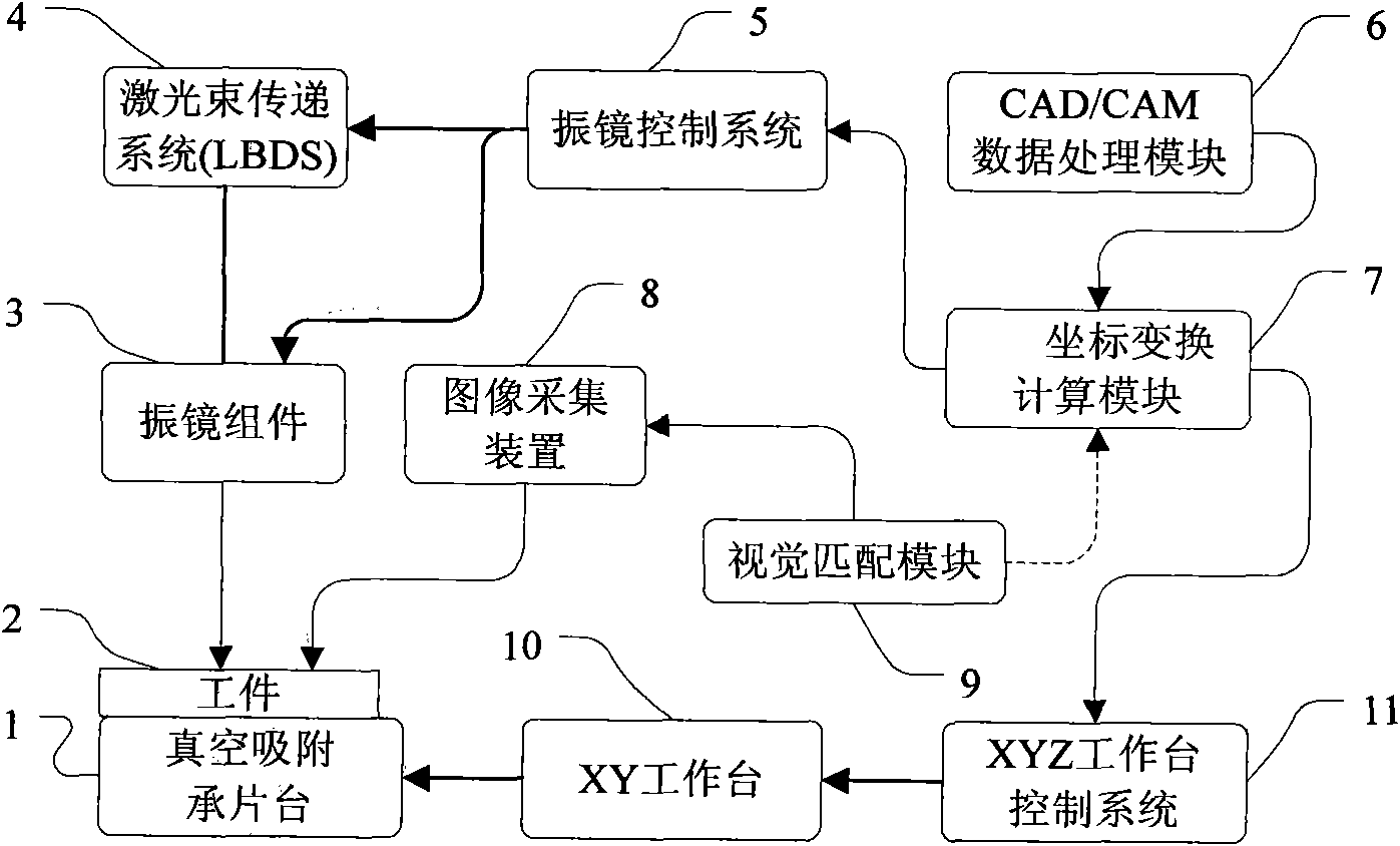
[0006] The purpose of the present invention is to provide a double-table driven laser processing machine and its processing method, which can be suitable for the processing of P1 process or P2 process of LTCC process, aiming at solving the lack of flexibility and low processing efficiency of existing mechanical punching machines And the problem of poor automatic visual alignment accuracy caused by the shrinkage and deformation of the green ceramic sheet after the second loading of the P2 process. The structure of the present invention is simple and reasonable, and the principle and processing method are unique; the use of the present invention can effectively increase production capacity and improve processing. Efficiency, quality assurance, cost reduction

Method used


Image

  • Double-workbench drive laser processing machine and processing method thereof
  • Double-workbench drive laser processing machine and processing method thereof
  • Double-workbench drive laser processing machine and processing method thereof

Examples


Embodiment Construction

[0062] The preferred specific embodiments described here are only used to explain the present invention, and are not suitable for limiting the present invention.

[0063] In this preferred embodiment, if image 3 As shown, the laser processing machine system includes:

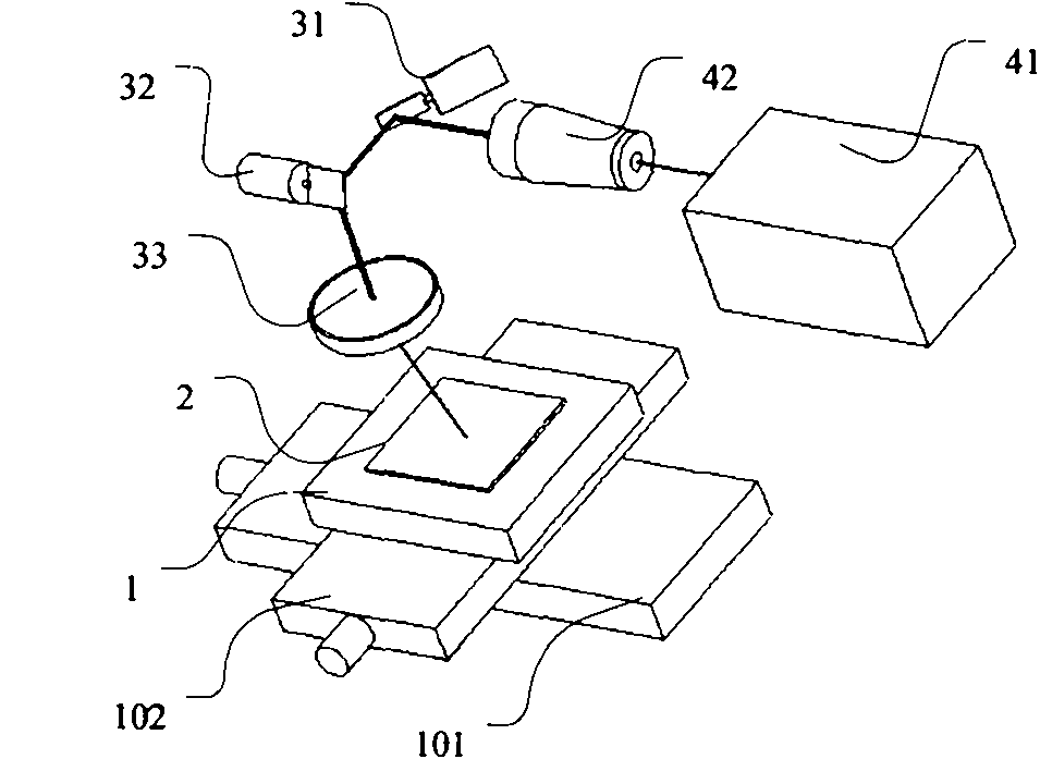
[0064] The first workbench, that is, the two-dimensional scanning galvanometer assembly 3, such as Figure 6 As shown, it consists of a first reflector 31 , a second reflector 32 , a telecentric f-θ lens 33 and a support frame 34 . Through the vibrating mirror control system 5, the laser marking process on the workpiece 2 is realized.

[0065] The second workbench is the XYZ workbench device. Such as Figure 4 As shown, the second workbench is composed of an XY workbench 10 and a Z-direction workbench 103 . Through the XYZ workbench control system 11, the movement and positioning of the vacuum suction substrate 1 (on which the workpiece 2 is adsorbed) in the horizontal plane and Z-direction laser focusing ...


PUM


Abstract

The invention provides a double-workbench drive laser processing machine and a processing method thereof, and relates to the technical field of laser precision processing equipment. The double-workbench drive laser processing machine is provided with a first workbench, a second workbench, a laser beam transfer device (LBDS), a vacuum adsorption chuck and an image acquisition device. The processing method comprises the following steps: carrying out P1 non-contraposition and P2 contraposition on the basis of a unified affine transformation model; mapping a workpiece coordinate space to a processing coordinate space, i.e. a first workbench processing coordinate and a second workbench processing coordinate; and transferring a CAD data pattern to the workpiece, thereby controlling a feature position error of the processed pattern within an ideal accuracy range. By using the invention, the working efficiency of the P1 procedure can be effectively enhanced and the problem of automatic visual contraposition accuracy caused by workpiece deformation in the P2 procedure can be effectively solved, thereby reducing the cost and enhancing the productive capacity. The invention has the advantages of simple structure, and unique principle and method. The invention is especially suitable to be used on a large-scale LTCC / HTCC production line of processing technology.

Description

technical field [0001] The invention belongs to the technical field of laser precision processing equipment, in particular to a double-table driven laser processing machine and a processing method thereof. Background technique [0002] In recent years, high-density packaging / assembly and high-density interconnect (HDI) technologies in the semiconductor industry have developed rapidly. As a high-performance HDI solution, LTCC (Low Temperature Co-fired Ceramics) packaging technology provides high-density integration and high reliability for single-chip or multi-chip module (MCM) packaging, and has been widely used in Optoelectronic communication devices, MEMS (micro-electromechanical systems) devices, biomedical chips, automotive electronics, microwave circuits, military T / R components, aerospace and other fields. [0003] Correspondingly, the technical level of today's large-scale LTCC process production line has the following characteristics: 8-inch green ceramic ribbon spe...

Claims


Application Information

Patent Timeline
IPC IPC(8): B23K26/36B23K26/42B23K26/08B23K26/06B23K26/064B23K26/38B23K26/402B23K26/70
Inventor 孟凡辉许志伟宋波张孝其赵志伟高爱梅刘红英王定临
Owner THE 45TH RES INST OF CETC
Learn More