Drilling fluid PLC automatic control system and control method thereof
What is Al technical title?
Al technical title is built by PatSnap Al team. It summarizes the technical point description of the patent document.
A technology of automatic control system and control method, which is applied in sequence/logic controller program control, electrical program control, construction, etc., can solve the problems of manual preparation of drilling fluid, avoid engineering quality accidents, and monitor technical parameters in real time , the effect of reducing production costs
Inactive Publication Date: 2012-10-03
DAQING JINGTAI PETROLEUM ENG TECH
View PDF1 Cites 1 Cited by
Summary
Abstract
Description
Claims
Application Information
AI Technical Summary
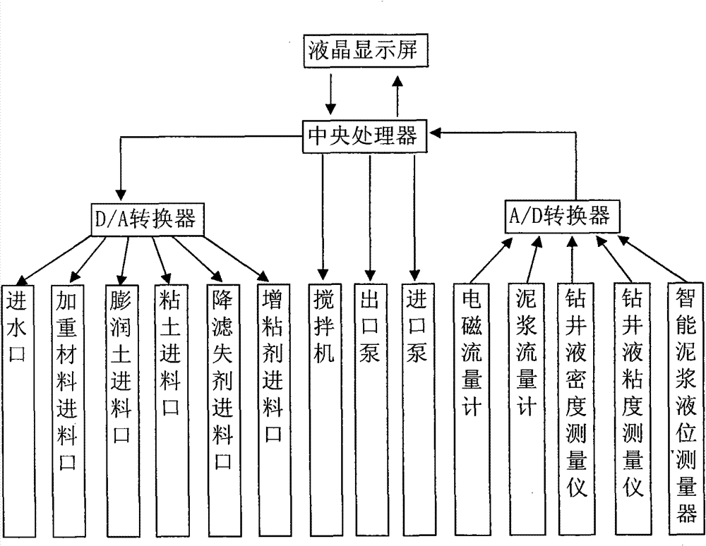
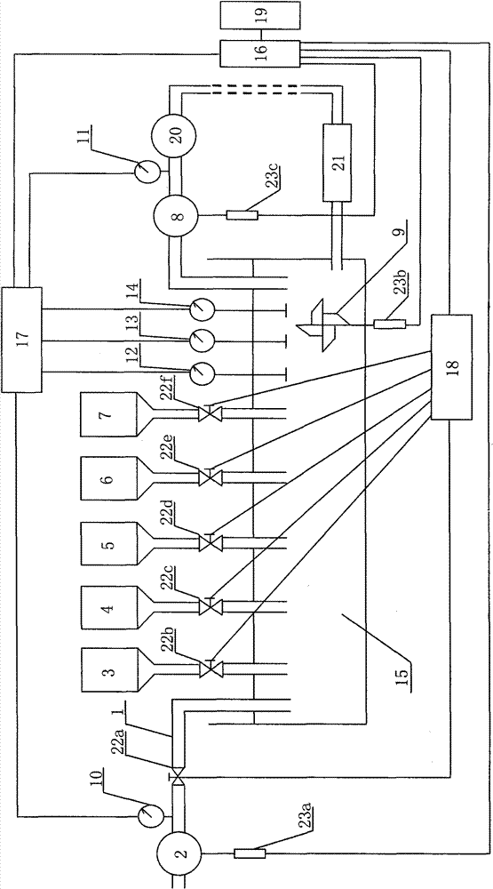
This helps you quickly interpret patents by identifying the three key elements:
Problems solved by technology
Method used
Benefits of technology
Problems solved by technology
[0005] The purpose of the present invention is to provide a kind of drilling fluid PLC automatic control system and its control method in view of the above problems, which can solve the problem of manual preparation of drilling fluid and fully realize automation
Method used
Image
Click on the blue label to locate the original text in one second.
Reading with bidirectional positioning of images and text.
Examples
specific Embodiment approach
[0013] Five, specific embodiment: the present invention will be further described below in conjunction with accompanying drawing:
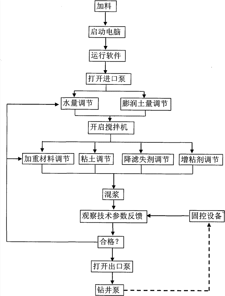
[0014] figure 1 It is the working block diagram of the PLC automatic control system in the present invention, figure 2 It is a schematic structural diagram of the automatic control system in the present invention, and the dotted line part in the figure represents the drilling cycle, combined with figure 1 , figure 2 As shown, the drilling fluid PLC automatic control system is used in conjunction with the drilling pump 20 and the solid control equipment 21. The system is composed of a central processing unit 16, an A / D converter 17, a D / A converter 18, and a liquid crystal display 19. The central processing unit, and the electromagnetic flowmeter 10, mud flowmeter 11, intelligent mud level measuring device 12, drilling fluid density tester 13, drilling fluid viscosity measuring instrument 14, mixer 9, clay feeding port 3, Bentonite inlet 4, we...
PUM
Abstract
The invention discloses a drilling fluid PLC automatic control system and a control method thereof, which are matched with a drilling pump and solid control equipment. The control system consists of a central processing unit, an A / D converter, a D / A converter, a liquid crystal display screen, an electromagnetic flowmeter, a mud flow meter, an intelligent mud level measurement device, a drilling fluid density tester, a drilling fluid viscosity measuring instrument, a blender, a clay feed inlet, a bentonite feed inlet, a weighting material feed inlet, a fluid loss agent feed inlet, a tackifier feed inlet, a water inlet, an inlet pump, and an outlet pump. The control method comprises that: the central processing unit sends a command to control the work of the water inlet, five feed inlets, the inlet pump, the blender and the outlet pump; the electromagnetic flowmeter, the mud flow meter, the intelligent mud level measurement device, the drilling fluid density tester, and the drilling fluid viscosity measuring instrument input the acquired data into a PLC; and the data subjected to PLC operation is displayed on the liquid crystal display screen. The control method can reduce the manpower and material resources needed by on-site liquid preparation and reduce the production cost.
Description
1. Technical field [0001] The invention relates to a PLC automatic control system and a control method thereof, in particular to a drilling fluid PLC automatic control system and a control method thereof. 2. Background technology [0002] Drilling fluid, commonly known as mud, plays a variety of very important roles in the drilling process, such as balancing the wellbore pressure, carrying cuttings, cooling the drill bit, consolidating the well wall and protecting oil and gas layers. In the past, the liquid preparation mainly relied on manual measurement of drilling fluid parameters, adding various materials according to the required technical parameters, so that the required liquid reached the technical indicators and satisfied the drilling construction. Therefore, a large number of technicians and workers need to be invested, and each link must be guarded by a special person, which is extremely inconvenient for operation and management. At present, the patent No. 20051010...
Claims
Application Information
Patent Timeline
Application Date:The date an application was filed.
Publication Date:The date a patent or application was officially published.
First Publication Date:The earliest publication date of a patent with the same application number.
Issue Date:Publication date of the patent grant document.
PCT Entry Date:The Entry date of PCT National Phase.
Estimated Expiry Date:The statutory expiry date of a patent right according to the Patent Law, and it is the longest term of protection that the patent right can achieve without the termination of the patent right due to other reasons(Term extension factor has been taken into account ).
Invalid Date:Actual expiry date is based on effective date or publication date of legal transaction data of invalid patent.