Collecting circuit for direct current bus

A DC bus voltage and acquisition circuit technology, which is applied in the direction of current collectors, circuit devices, battery circuit devices, etc., can solve the problem of unbalanced real-time voltage acquisition and other problems, so as to avoid the influence of time and environment, improve sampling accuracy, Improving the effect of real-time performance

Active Publication Date: 2012-05-23
SHENZHEN SUNFAR ELECTRIC TECH
View PDF0 Cites 0 Cited by
  • Summary
  • Abstract
  • Description
  • Claims
  • Application Information

AI Technical Summary

Problems solved by technology

[0005] The technical problem to be solved by the present invention is to provide a method that can not only improve the sampling accuracy of the sampling voltage but also improve Follow-up DC Bus Acquisition Circuit for Voltage Acquisition

Method used


Image

  • Collecting circuit for direct current bus
  • Collecting circuit for direct current bus
  • Collecting circuit for direct current bus

Examples


Embodiment Construction

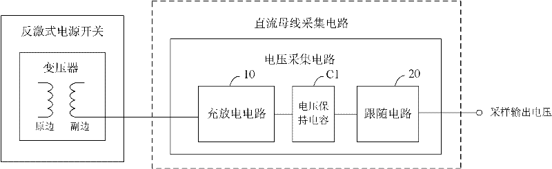
[0042] Such as figure 1 Shown is the structural block diagram of the first embodiment of the DC bus acquisition circuit of the present invention. The DC bus acquisition circuit is used to acquire the DC bus voltage of the flyback switching power supply. The DC bus acquisition circuit includes a forward connection connected to the flyback The voltage acquisition circuit of the secondary side of the transformer in the type switching power supply, the voltage acquisition circuit includes a voltage holding capacitor C1, a charging and discharging circuit 10 and a follower circuit 20, and in the forward period of the flyback switching power supply, the charging and discharging circuit 10 adopts DC The bus voltage charges the voltage holding capacitor C1, and at the same time discharges the voltage holding capacitor C1; during the flyback period of the flyback switching power supply, the charging and discharging circuit 10 prevents the voltage holding capacitor C1 from discharging; t...


PUM


Abstract

The invention relates to a collecting circuit for a direct current bus, which is used for collecting direct current bus voltage of a flyback converter. The collecting circuit for the direct current bus comprises a voltage collecting circuit which is connected to a secondary coil of a transformer of the flyback converter by adopting a forward mode, wherein the voltage collecting circuit comprises a voltage sustaining capacitor, a charge and discharge circuit and a follower circuit. In a forward period of the flyback converter, the charge and discharge circuit charges the voltage sustaining capacitor according to the collected direct current bus voltage, and simultaneously, the voltage sustaining capacitor discharges to realize quick charging and quick discharging and improve the real-time of voltage collection; and in a flyback period of the flyback converter, the charge and discharge circuit stops discharging of the voltage sustaining capacitor, and the voltage sustaining capacitor cannot discharge without a discharge circuit, so that excellent sustaining characteristic can be realized, and the sampling accuracy of sample voltage can be improved.

Description

technical field [0001] The invention relates to the technical field of switching power supplies, and more specifically relates to a DC bus acquisition circuit for flyback switching power supplies. Background technique [0002] A flyback switching power supply refers to a switching power supply that uses a flyback high-frequency transformer to isolate the input and output circuits. The so-called "flyback" specifically means that when the input is high level and the switch tube is turned on, the inductance connected in series in the output line is in a discharge state. On the contrary, when the input is high level and the switch tube is turned off, the inductance connected in series in the output line The inductor is charged. [0003] The DC bus sampling circuit of the flyback switching power supply only works in the forward cycle of the switching power supply. Therefore, to ensure that the DC bus voltage can be effectively collected during the forward and back cycles, it is ...

Claims


Application Information

Patent Timeline
Patent Type & Authority Patents(China)
IPC IPC(8): H02M7/217H02J7/00G01R19/00
Inventor 罗维
Owner SHENZHEN SUNFAR ELECTRIC TECH
Why Eureka
Try Eureka