Thermoelectric power generator and power generating system using thermoelectric power generator

A technology for thermoelectric power generation and power generation system, which is applied to generators/motors, steam engine installations, ocean energy power generation, etc. It can solve the problems of no heat energy recovery, unavoidable cost increase, and complex overall structure, so as to avoid cost increase, Easy maintenance and small space requirements

Inactive Publication Date: 2010-10-27
JAPAN MARINE UNITED CORP
View PDF1 Cites 9 Cited by
  • Summary
  • Abstract
  • Description
  • Claims
  • Application Information

AI Technical Summary

Problems solved by technology

[0010] However, in figure 1 In the ocean temperature difference power generation system as shown, it is necessary to: evaporator 2, first turbine 4, first generator 5, heater 6, second turbine 7, second generator 8, regenerator 9 , the condenser 12, the first working fluid pump 16, the second working fluid pump 18, etc., the overall structure becomes very complicated, it is difficult to avoid cost increases, and there are many rotating parts, and regular maintenance is also indispensable. Practical
[0011] On the other hand, in figure 2 In the power plant as shown, the thermal energy recovery device becomes large-scale, and the seawater, which is the cooling water heated up by depriving heat from the steam in the steam condenser 24, is directly discharged into the sea, and heat recovery is hardly performed.

Method used


Image

  • Thermoelectric power generator and power generating system using thermoelectric power generator
  • Thermoelectric power generator and power generating system using thermoelectric power generator
  • Thermoelectric power generator and power generating system using thermoelectric power generator

Examples


Embodiment Construction

[0062] Hereinafter, embodiments of the present invention will be described with reference to the drawings.

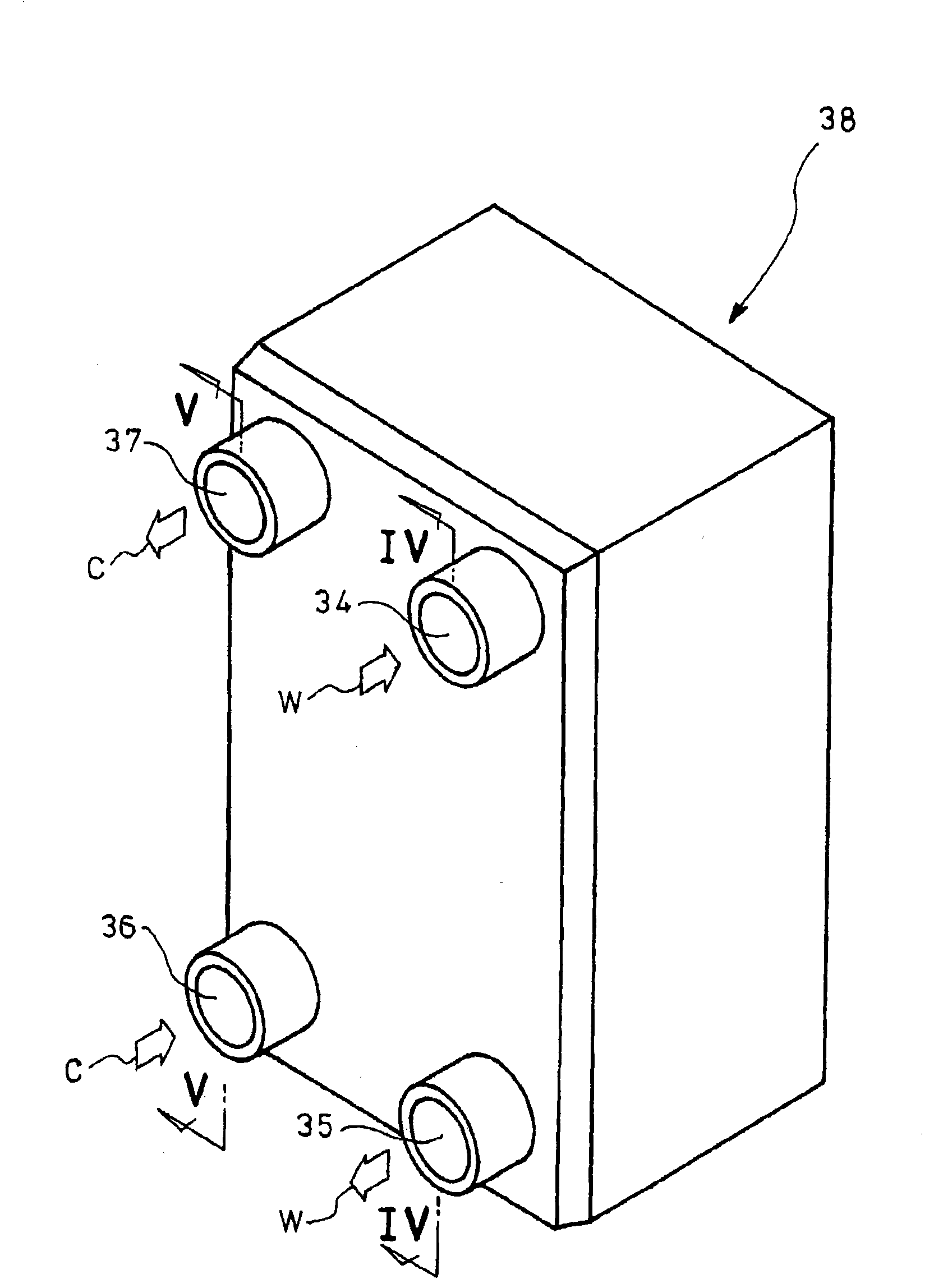
[0063] Figure 3 ~ Figure 8 It is an embodiment of the present invention, wherein the thermoelectric elements 27 with P-type thermoelectric semiconductor elements 25 and N-type thermoelectric semiconductor elements 26 alternately arranged side by side are enclosed in the heat transfer plate 30 in a manner sandwiched by electrodes 28 and insulators 29 In order to form a plate-shaped thermoelectric generating unit 31, a plurality of plate-shaped thermoelectric generating units 31 are stacked, and high-temperature fluids are alternately formed between the plate-shaped thermoelectric generating units 31 with each of the above-mentioned plate-shaped thermoelectric generating units 31 as a boundary. The first space 32 through which W flows and the second space 33 through which the low-temperature fluid C flows are formed by connecting the openings formed in the above-mentione...


PUM


Abstract

Provided is a thermoelectric power generator which can efficiently perform thermoelectric conversion (power generation) from a fluid having a temperature difference, with easy maintenance and a small space required, for stably supplying power at low cost compared with conventional generators. A power generating system using such thermoelectric generator is also provided. In a thermoelectric element (27), P-type thermoelectric semiconductor elements and N-type thermoelectric semiconductor elements are alternately arranged in parallel. The thermoelectric element is sealed in a heat conductive plate (30) to be sandwiched by an electrode and an insulator, and a plate-like thermoelectric power generating unit (31) is formed. A plurality of plate-like thermoelectric power generating units are laminated, and first spaces (32) wherein a high-temperature fluid (W) circulates and second spaces (33) wherein a low-temperature fluid (C) circulates are alternately formed between the plate-like thermoelectric power generating units. By gathering openings formed on the plate-like thermoelectric power generating units (31), a first inflow channel (34) and a first outflow channel (35) for flowing in and out the high-temperature fluid (W) to and from the first spaces (32), and a second inflow channel and a second outflow channel for flowing in and out the low-temperature fluid (C) to and from the second space (33) are formed.

Description

technical field [0001] The present invention relates to a thermoelectric power generation device and a power generation system using the thermoelectric power generation device. Background technique [0002] Conventionally, a power generation system that utilizes the temperature difference between the warm seawater on the ocean surface and the cold seawater in the deep sea has attracted attention as a technology that effectively utilizes natural energy. [0003] This ocean temperature difference power generation system such as figure 1 As shown, it is composed of: a warm seawater pump 1, which draws warm seawater from the ocean surface; an evaporator 2, which evaporates the mixed liquid of ammonia / water by utilizing the heat of the warm seawater drawn up by the warm seawater pump 1; a gas-liquid separator 3. The mixed liquid of ammonia / water evaporated by the evaporator 2 is separated into ammonia water and ammonia / water vapor; the first turbine (turbine) 4 is introduced int...

Claims


Application Information

Patent Timeline
Patent Type & Authority Applications(China)
IPC IPC(8): H02N11/00
CPCF01K25/10H01L35/30H02N11/002Y02E10/34Y02E10/30H10N10/13
Inventor 粟岛裕治吉本治树
Owner JAPAN MARINE UNITED CORP
Why Eureka
Try Eureka